Download
1 / 16
160 likes | 299 Vues
Lift-On/Lift-Off Throughput Improvements. Frank Leban Naval Surface Warfare Center Carderock Division. Supporting Data >30% of Cycle Time Consumed by Final Positioning. NOT strictly driven by sea state Can apply to containers in cell guides. Commercial Pier-side Operations*.

E N D
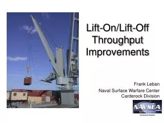
Lift-On/Lift-Off Throughput Improvements Frank Leban Naval Surface Warfare Center Carderock Division
Supporting Data>30% of Cycle Time Consumed by Final Positioning • NOT strictly driven by sea state • Can apply to containers in cell guides Commercial Pier-side Operations* JLOTS 04 New Horizons * Data courtesy of MacGREGOR Cranes, AB
Improved Container Lift Frame (ICLF) Design/Build Progress
Program Objectives • To design and build an ICLF similar to that previously tested but with improved features • - Higher restraining forces to be provided if possible by incorporating higher horsepower winch motor and components • - System to be powered by 460-volt/15 amp/3-phase supply available at crane hook (Increasing motor size from previous 2 hp up to a maximum of 5 hp will depend on starting and operating current limitations) • - Winch speed must match maximum hook drop rate of 120 ft/minute • - System should be explosion proof (Standard yet to be specified)
Electric Motor Selection • Power is turned on and off and phase is reversed by controls in the crane control cab • Explosion proof motors built to NFPA and NEC Class I, Division 2 standards (which includes flammable liquids and gases which are not normally present) are available with built-in electro-magnetic brake • To control toque down to zero speed, either a controllable clutch or electronic torque control drive (VFD) must be used • VFD must be able to be started and stopped by turning off power source.Drive “boot up” time must be considered as the drive will have to go through this EVERY time the direction is changed or the drive is stopped and restarted. • Drive and all needed circuitry must be enclosed in an explosion proof enclosure. Cooling needs to be addressed.
Undesirable Characteristics of VFD Eliminates its selection for use • VFDs are not designed to operate in extreme temperature or humidity conditions that will occur in this application • Can be fitted in a protective explosion proof casing but heat dissipation may be a problem. Casing becomes large, heavy and expensive • Possible delays as the VFD completes its power up sequence before operation may compromise its safe use • Frequently cycling power on and off may damage VFD and lead to early failures
Other Powering Possibilities • Available electrical power may be converted to other forms of energy including mechanical, hydraulic and pneumatic • Mechanical energy may be stored in springs and released in a controlled manner - no convenient motors identified • Hydraulic pumps, motors, accumulators and controls available - high pressure systems are prone to leakage • Pneumatic pumps, motors, accumulators and controls available - low pressure systems have low efficiency
Pneumatic Motors Parker Air Motors • Typical Types and Uses- Starter Motors - Winches • Main types have rotary vanes or radial pistons and can be reversible • Can be frequently started, stopped and run in stalled condition without damage • Exhausting air is noisy unless motor is fitted with a suitable silencer • Means must be provided to filter air and eliminate moisture and possibly add lubrication
Status • Design of mechanical components have been prepared using “SolidWorks” solids modeling CAD program • Finalization of design requires check of measurements of actual lift frame which is now due for delivery in mid-February 2005 • A pneumatic motor is an option for winch but more evaluation is required
Container w/ Guides Guides would be put in place at same time as twistlocks – Consistent with commercial practice
Status • Proof-of-concept test articles to be delivered in March (MacGREGOR-CONVER) • Need to develop procedures for use & assess effect on throughput • Flickertail State w/ crew and Naval Cargo Handling Battalion • Potential for use in TURBOCADS ‘05 • Other concepts to be considered
Questions?Acknowledgements –Mike Plackett, QEDRyan Hayleck, NSWCCD