Heat Transfer
Heat Transfer. To heat up or to cool down is always needed in a chemical plant Part of energy problem Source of energy: coal, natural gas, shale gas, nuclear reactor, solar, wind, hydraulic, geothermal etc. waste heat recovery transfer media: usually steam

Heat Transfer
E N D
Presentation Transcript
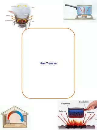
Heat Transfer • To heat up or to cool down is always needed in a chemical plant • Part of energy problem • Source of energy: coal, natural gas, shale gas, nuclear reactor, solar, wind, hydraulic, geothermal etc. • waste heat recovery • transfer media: usually steam • efficiency: can you estimate it for every transfer?
Tubular heat exchanger: heat transfer coefficient h = f(Re); purpose - heating or cooling; existing in each factory; steam-electricity co-generation system汽電共生; • Drying: operation; sources of heating: conduction (less frequently), convection (hot air), radiation (lamp (wavelength), solar light, xenon lamp, etc) C: Heat Transfer Experiments Picture taken from Wikipedia
C1: Tubular Heat Exchanger • Very traditional; steam is often used as the heating source; boiler to generate steam (may need licence to operate this equipment) • Basic equation: q = h A T • Overall heat transfer efficient (Uo or Ui): outside heat transfer coefficient ho, outside scale resistance Ro, tube heat transfer resistance kw, inside scale resistance Ri, inside heat transfer coefficient hi (scale resistance usually small) • 1/Uo = 1/ho + Ro + xw/kw (Do/Dm) + Ri (Do/Di) + 1/hi (Do/Di); Dm = log mean dia.
liquid-side film heat transfer coefficient: ho, hi; • usually assume other heat transfer resistance negligible, Q = m Cp (T out – T in) = hi Ai Tlm, with Tlm = (T2 - T1)/log (T2/T1) • we may have co-current flow, counter-current flow, etc. • In general: Nu = F(Re, Pr, L/D) • Nu = Nusselt number = h D/k =convective heat transfer coefficient/conductive heat transfer coefficient • Pr = Prandtl number = viscous diffusion rate/thermal diffusion rate = Cp/k
Many correlations proposed: e.g. Colburn j -factor: Nu = 0.023 Re^0.8 Pr^1/3 (for Pr: 0.7 – 160) • L/D < 60: entrance effect may not be neglected • A simplified correlation: hi = a V^0.8 (1+ 0.0146 T) • steam: saturated, superheating, super-cooling • vent: safety purpose • Source of heat: natural gas, diesel fuel (C8 – C21; BP: 200 – 320oC), coal, solar, waste heat, etc. • heavy oil: very viscous, > C60, high percentage of aromatics, naphthalene, high amounts of NSO (chemical element); bottom product from distillation
Steam trap: to discharge condensate, non-condensable gases, with minimum loss of steam; usually automatic valve;
C2: Drying • Simultaneous heat and mass transfer • Free moisture content, meaning some water may be chemically bond to solid material, may need “dehydration” • moisture inside pores: may be slow to evaporate • from air point view: percentage humidity (relative to saturation humidity) • wet bulb temperature (adiabatic saturation temperature) vs dry bulb temperature vs dew point; • humidity chart
Wet bulb globe temperature: originally developed by US marine corps. To determine heat stress of work • WBGT = 0.7 Tw (wet bulb temp., humidity effect)+ 0.2 Tg (solar radiation) + 0.1 Td (dry bulb temp)
Adiabatic saturation temperature – wet bulb temperature • Air at T, H; water sprayed into to RH = 100%, system T = adiabatic saturation temperature • cs (T-Ts) + Hs = Hs s; (H-Hs)/(T-Ts) = -cs/s adiabatic saturation line (on T-H diagram) • Air at T, H flow over wet bulb to read T = wet bulb temperature • hy (T-Tw) = Mb k w (Hw-H); (H-Hw)/(T-Tw)= - hy/(Mb k w) psychrometric line • cs hy/Mb k Lewis relation
pre-heat period, constant rate period, falling rate period (first & second falling rate); • constant rate period reach “critical point”, then mass transfer becomes important
Dryer: with hot air drying + IR heater • For industrial operation: usually in continuous mode (on a belt), tunnel kiln, etc.
Pictures taken from: Vandenbroek International website; drum dryer • Spray drying; (others: fluidized drying, etc)
In a typical phase diagram, the boundary between gas and liquid runs from the triple point to the critical point. Regular drying is the green arrow, while supercritical drying is the red arrow and freeze drying is the blue. (Wikipedia)