Download
1 / 45
460 likes | 583 Vues
Explore the development of cast modular connections for seismic-resistant steel frames, addressing design challenges and enhancing seismic performance. Discover the structural system, background on frame action, energy dissipation mechanisms, solutions for connection failures, and prototype experiments. Learn about the modular node concept, partial-restrained frames, simplified mechanics models, and beta prototype features.

E N D
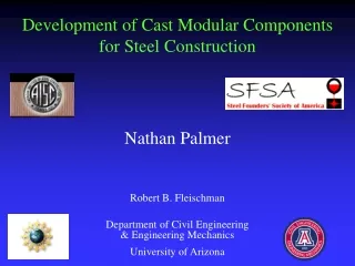
Development of Cast Modular Connections for Seismic-Resistant Steel Frames by Robert B. Fleischman Ali Sumer, Xuejun Li, Nathan Palmer, Ian Cameron Department of Civil Engineering & Engineering Mechanics University of Arizona
Industry Partners • Varicast, Inc., Portland OR • Able Steel Fabricator Inc., Mesa AZ
Cast Modular Connections for SMFs MODULAR NODE MODULAR CONNECTOR
The Structural System: Steel Special Moment Frame (SMF) • Required in high seismic zones • Popular because of architectural advantages and ease of construction • Widely viewed as most reliable and ductile seismic lateral system • Lateral load resistance provided by rigid frame action using welded connections
Story Drift Load Region of high moment requires rigid connection h L Background:Frame Action
Background: Seismic-Resistant Design FORCE recoverable elastic F F service EQ X DRIFT non-recoverable • Cannot outstrength earthquake (economic/reliability standpoint) • Create special regions (details) that act as structural “fuses”, limiting the forces (usually through yielding of steel) • Yielding dissipates the earthquake energy • “Stretch but not break”
Plastic Rotation absorbs & dissipates EQ energy Panel Zone Shear due to Beam Moments Plastic Shear Distortion dissipates EQ energy. Beam End Moments due to Lateral Load Beam Plastic Hinge Area Energy Dissipation Mechanism for SMFs
Northridge Earthquake, January 17, 1994 • More than 100 Special Moment Frames (SMFs) suffered extensive brittle fracture (no yielding)
Main factors causing connection failure • Weld and HAZ possess low toughness • Flanges at weld attract high shear force • High triaxial restraint at column flange/beam flange interface • Column flange stress transferred in through-thickness direction • In other words, these connection’s inherent configuration is not conducive to ductile behavior, and to make matters worse, the weld region is placed at this location.
NSF CAREER Award 01-96120 Proposed Solution • Specially configure the connection region for optimal seismic performance. • Eliminate the field weld from the critical region. Traditional rolled shapes do not have the versatility in form to meet this objective. It is, however, a natural application for steel castings.
Modular Node Concept: Fabrication and Erection Column Shop Weld Field Weld Beam Beam PZ-MN Field Weld Shop Weld Column
80 70 60 50 True Stress (ksi) 50 ksi steel 40 43 ksi steel 30 True Stress 20 True Strain 10 0 0.00 0.05 0.10 0.15 0.20 0.25 0.30 0.35 True Strain Material Requirements Nominal Requirement As provided by Varicast
Research Program Analytical Experimental
Field Weld Panel zone weak relative to beam Field Weld PZ-MN Configuration Web connecting detail
Deformation of Panel Zone: Traditional Joint Kinking of Column Flange P
Column Flange Kinking in Connection FEMA 350 minimum PZ relative strength Implied allowable column flange curvature value Weaker panel zone relative to beam
R Filleted cruciform PZ-MN Configuration Web connecting detail
Reducing Column Flange Curvature Allowable Curvature
Reduced column section Reduced link section PZ-MN Configuration Link region No web in beam link Web connecting detail
Flange stiffener Web connector PZ-MN Configuration Web connecting detail
Mitigation of Weld Stress Web Connector
PZ-MN-01 Monotonic Test Py (EXP) = 70 Py (FE) =76
PZ-MN-02 FEMA Cyclic Test Survived 12 additional cycles at max amplitude Qualifying Drift Angle for Strength Degradation Qualifying Drift Angle: Complete Failure
Modular Connector (MC) • Objective – Dissipate EQ energy in the connector rather than in main members. • Shop-weld or bolt to beam • Field bolt to column
Partially-Restrained Frames (PRFs) Bolted connections are typically less stiff and strong than welded connections, and thus are used throughout the structure.
D T M C M=Tdbm To evaluate the overall connection while examining only single connector in tension: =D/ dbm Simplified Model of Mechanics dbm
Bolt Prying of Traditional Tee-Stub Plastic Hinge Locations T=Q+P
ALPHA PROTOTYPE In comparison to traditional connection: • Similar stiffness and strength • Reduced bolt prying • No bolt failure • Improved ductility
Comparison of Plastic Damage Regions: Connector vs. Traditional Connection
Beta Prototype Features: • Variable arm width instead of thickness. • Design based on improved analytical model. • Quality control and high value steel in castings.
Effect of Arm Shape failure strain ADAS WT WT MC 3 2.5 MC 2 1.5 ADAS 1 0.5 0 0 0.1 0.2 0.3 0.4 WT Translating Boundary MC ADAS Fixed Boundary EQUIVALENT PLASTIC STRAIN Isometric View
MC Half-scale Prototype Castings Specimen prepared with pull plate and strain gages MC with Base MC without Base
Global Results: MC vs. WT DUCTILE FAILURE IN MC MC 7/8" A325 Bolt BOLT FAILURE
Comparison of Constant Amplitude Tests Cycles to failure:19 WT 0.72 0.00 Cycles to failure:44 Amplitude (inch) MC 0.72 0.00 Loading History
MC without Base MC – No Base WT
Conclusions Steel castings have shown great promise as special energy-dissipating details in steel moment frames in high seismic zones. These modular designs exhibited: • Superior ductility w.r.t. traditional connections • Stable and efficient energy dissipation • Increasing strength due to work hardening • Reliability and repeatability
Future Work The NSF CAREER Award Grant extends until May 2003. The UA research team plans to continue work in this area until 2005. This work will include: • Qualification testing of family of PZ-MN • Full-scale testing of MC • Development and full-scale testing of PH-MN • Extension of MC concept to PT Systems