Download
1 / 42
450 likes | 553 Vues
Project outlines the development of modular cast components for steel construction, funded at $347,000 to enhance efficiency and safety in steel erection. Meeting agendas cover various connection candidates and a discussion on modular systems for automated construction. Innovative splice designs and mechanisms such as eye splices and quick connectors are explored to optimize structural integrity. Research focuses on self-guided, self-locking connections, aiming to streamline steel assembly processes.

E N D
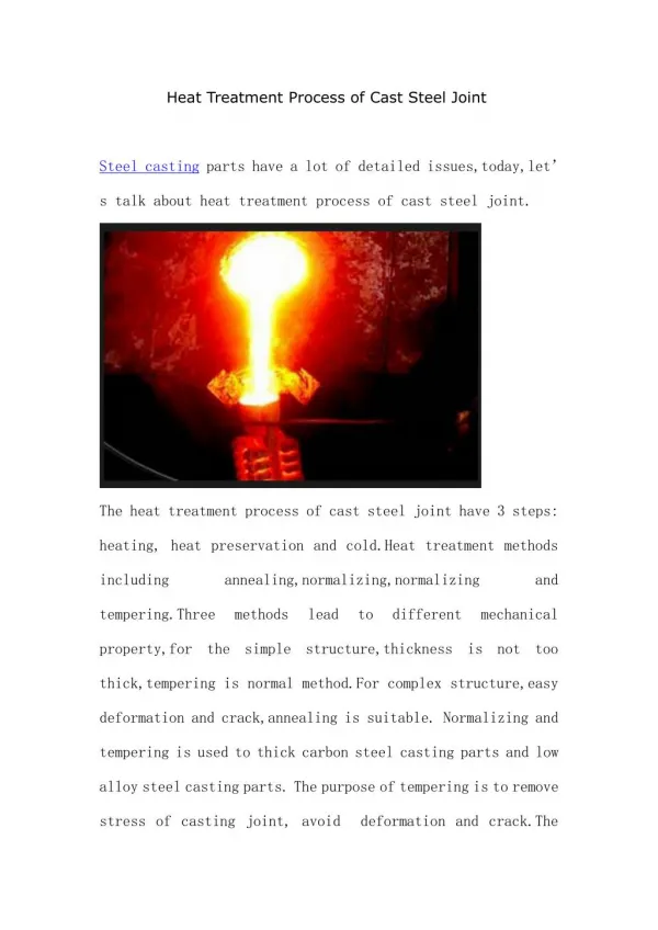
Development of Cast Modular Components for Steel Construction Nathan Palmer Robert B. Fleischman Department of Civil Engineering & Engineering Mechanics University of Arizona
Industry Partners • American Institute of Steel Construction • Steel Founder’s Society of America
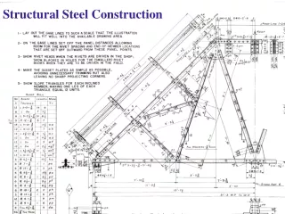
Background • UA, AISC and SFSA submitted proposal to NSF for $386,000 in January 03 • Objective of proposal is to develop modular cast components for use in steel construction • Proposal funded at $347,000; Effective date October 2003 • RBF, TS, DP, RM meet October 2003 to outline target areas • RBF,TS meet with NIST October 2003 to discuss opportunities for modular connections to facilitate or automate the steel erection process • NP starts on project late October; develops trial candidates in target areas • Research Meeting #1: December 19, 2003
Meeting Agenda I.Morning Discussion: Connection Candidates A.)Column Splices 1.)Wide-Flange Column Splices 2.)Tube Column Splices 3.)Wide-Flange to Square Tube Column Splices ·Manually Guided ·Self-Aligning ·Self-Locking B.)Beam to Column Connections 1.)Tube to Tube (Square and Round) 2.)Tube to Wide-Flange Beam 3.)Weak-Axis Connections ·Full- Moment Connections, Shear Connections ·Self-Aligning ·Seismic ·Full Node, Connectors C.)Bracing/Trusses 1.)Fixed Angle Gusset Plates 2.)Variable Angle Gusset Plates ·Wide-Flanges ·Tubes D.)Column Bases 1.)Wide-Flanges 2.)Tubes ·Pinned Base, Fixed Base ·Self-Guiding ·Self-Locking II.) Afternoon Discussion: Modular System for Automated Construction A.)Identification of Candidate (prototype) structures -Moment frame, Braced frame, Steel core, Staggered Truss, Other? B.)Current Procedures: Erection Process for the Entire Structure -Time and Cost -Sequencing -Tolerances -Plumbing C.)Approach: -self-guided vs. assisted -self-locking vs. secured -low tolerance vs. adjustable -Stick erection vs bay D.)Benefits to self-guided, self-locking, members -Time , Cost, Safety E.)Integrations with NIST Program -Timeline -Deliverables -Creation of Scaled models -Verification of Concept Lunch: 12 noon – 1pm
Initial Candidates Category A: Column Splices • A.) Column Splices • 1.) Wide-Flange Column Splices • 2.) Tube Column Splices • 3.) Wide-Flange to Square Tube Splices • Manually Guided • · Self-Aligning • · Self-Locking
version 2: connection version 1: guides • clips permit +/- 2” out of alignment in plan (2-ways) • erection bolts secure top column • perform field weld A.1 Wide-Flange Column Splices Candidate A.1.a: Angled Tabs • large tabs shop welded to lower column • clips permit +/- 2” out of alignment in plan (2-ways) • splice completed with field bolting or welded alternative
A.1 Wide-Flange Column Splices Candidate A.1.b: Keyed Splice Description • Two complementary pieces: one with notch; one with key • Shop welded to columns • Fits range of column sizes with same T-Distance • Key provides shear transfer; novel configuration permits moment transfer thru bolt tension
A.1 Wide-Flange Column Splices Candidate A.1.b: Keyed Splice Features • Bolts self-align (no alignment problems) • Reduced material compared to base-plates • No preparation to WF before welding • Has application as girder splice and beam to column moment connection
A.1 Wide-Flange Column Splices Candidate A.1.c: Eye Splice Description • Flange forces carried in quad-shear • Individual connector - easy to cast, difficult to align • Shop welded to each column
A.1 Wide-Flange Column Splices Candidate A.1.c: Eye Splice Description • Two solid pieces that ensure alignment • Three erection bolts in sandwiched web • Tapered web for alignment of flanges • Shear transfer provided by tapered pin and bushing; pin end threaded to lock
A.1 Wide-Flange Column Splices Candidate A.1.c: Eye Splice Pin Description • Three piece system • Threaded end of tapered pin for a nut • Expanding diameter with torque of nut which provides tight fit in eye-hole
A.1 Wide-Flange Column Splices Candidate A.1.d: Tendon Splice Description • Conical cavity shop-welded to web of bottom column • Conical tendon shop-welded to upper column • Tight fit – wedging forces to hold in place • Easy to cast, can be utilized on any size column with a scaling adjustment • Has applications as column base connection
A.1 Wide-Flange Column Splices Quick Connector Locking Mechanism #1 Description • Locking “hammer” mechanism that requires a pivoting shear pin • Hammers form small compression struts which rely on the shear strength of the pin • Shop welded to bottom column
A.2 Square Tube Column Splices Candidate A.2.a: Flanged Collar Splice Description • Modified Base-plate with self-aligning capability irregardless of tube wall thickness • Shop welded (either fillet of full-penetration welds) • Doubly symmetric hole patterns
A.2 Square Tube Column Splices Candidate A.2.a: Flanged Collar Splice Indentation for tapered lip Tubes inserted for fillet weld around perimeter
A.2 Square Tube Column Splices Candidate A.2.b: Transverse Pin Splice Description • Utilizes easy two-pin connection • Quad-shear feature • Columns shop welded to castings • Holds a somewhat self-aligning feature • Dimensions are that of the tube (no extrusions)
A.2 Square Tube Column Splices Candidate A.2.c: Finger Splice Description • Multiple “finger joints” which provide 12 shear planes per bolt • Minimal bolting required • Each casting is shop welded to column • End “fingers” are longer to facilitate alignment • Can develop full member strength
A.2 Square Tube Column Splices Candidate A.2.d: Cruciform Splice Description • Cruciform shape allows for bolting access • Two bolts per face loaded in double shear • All shop welds • No reduction in moment of inertia or strength • Pieces can possibly be recessed within dimension of the tube
A.2 Square Tube Column Splices Candidate A.2.e: Bolted Insert Splice Description • Cast insert with recessed nut holders • Insert has circular core to facilitate alignment • Insert is tack welded inside upper column prior to construction • Bottom casting has tapered conical pin as is shop welded to lower column • Full member capacity is reached thru field bolting
A.2 Round Tube Column Splices Candidate A.2.f: Flanged Collar Splice Description • Complimentary top and bottom castings to ensure alignment of bolt holes • Self-aligning taper • Tube can be inserted into casting or match diameter of casting to allow for full-pen weld • Full moment transfer capability Tube shown inserted
A.2 Round Tube Column Splices Candidate A.2.g: Knife Plate Splice Description • Two castings full-pen welded to tubes • Taper on bottom casting to help guide into place • Tabs sandwiched between vertical plates to allow for double shear bolting or field welding • Full moment transfer; increased moment of inertia
A.2 Square Tube Column Splices Quick Connector Locking Mechanism #2a Description • Thin cantilevers with triangular “latching” ends • Cantilevers bend inward (elastically) under gravity load of upper column • Slots cut into HSS tube in shop • Field weld or bolt necessary after erection is completed
A.2 Square Tube Column Splices Quick Connector Locking Mechanism #2b Description • Same concept without cantilever base • One universal casting • Shop or field bolted to lower column • Shorter cantilever extending from end of tube
A.3 WF to HSS Column Splices Candidate A.3.a: Bolted Plate Splice Description • Bottom base-plate shop welded to WF with center aligning hole • Top base-plate shop welded to HSS tube and slips into aligning hole of bottom plate while “saddling” WF web • Bolting pattern directly in line with tube faces which puts bolts in tension • Nut locations are recessed and will hold nuts while tightening bolts from below
A.3 WF to HSS Column Splices Candidate A.3.a: Bolted Plate Splice
Initial Candidates Category B: Beam to Column Connections Beam to Column Connections 1.) Tube to Tube (square) 2.) Tube to Wide-Flange Beam (square and round) 3.) Weak-Axis Connections · Full- Moment Connections, Shear Connections · Self-Aligning · Seismic
B.1 Square Tube Beam to Square Tube Column Connections Candidate B.1.a: Simple Ledge Description • Cast ledge is shop welded to column • Tube beam must be prepared by drilling hole of proper diameter in bottom face • Simply supported • May be required to field weld tube onto ledge
B.1 Square Tube Beam to Square Tube Column Connections Candidate B.1.b: Full Moment Node Description • Resists moment thru bearing surfaces • Node can be welded to column or could possibly act simultaneously as a column splice • Inserting fixtures can be adapted to fit tubes and WF’s
B.1 Square Tube Beam to Square Tube Column Connections Candidate B.1.b: Full Moment Node
B.2 Tube column to WF Beam Connections Candidate B.2.a: Full Moment Collar Description • Resists moment thru bearing surfaces • Node can be welded to column or could possibly act simultaneously as a column splice • Inserting fixtures can be adapted to fit tubes and WF’s • No loss is moment of inertia in beam adapter
B.3 Weak-Axis Connections Candidate B.3.a: Welded Adapter Description • Adapter is inclined to allow for weld access • Bottom adapter is shop welded to column • Top adapter is shop welded to beam • Combination allows for any size beam • Field welds required at bottom flange and at the top adapter/column interface
B.3 Weak-Axis Connections Candidate B.3.b: Dual-Eye Description • R
B.3 Weak-Axis Connections Candidate B.3.b: Dual-Eye Description • R
B.3 Weak-Axis Connections Candidate B.3.b: Dual-Eye Description • R
B.3 Weak-Axis Connections Candidate B.3.c: Full Moment Quarter Node Description • Resists moment thru bearing surfaces • Connector can be shop or field bolted to column • Inserting fixtures can be adapted to fit tubes and WF’s • No loss is moment of inertia in beam adapter • Connector is confined within flanges
Initial Candidate Category C: Bracing Connections
Initial Candidates Category D: Column Bases Description • Typical Base-plate with four tie-down holes and a tapered centerpiece • Cast studs which hold nut from rotating and are shop welded to bottom of base-plate • After studs are welded, column base can be cast in concrete
Initial Candidates Category D: Column Bases Description • Complimentary top base-plate with prepared WF for welding and a tapered centerpiece • Top and Bottom base-plates will align and tie-down rods can then be tightened
Initial Candidates Category D: Individual Tie-downs
Seismic Design Guide plates Double-Arm PH-MN
Conclusions Steel castings have shown great promise as special energy-dissipating details in steel moment frames in high seismic zones. These modular designs exhibited: • Superior ductility w.r.t. traditional connections • Stable and efficient energy dissipation • Increasing strength due to work hardening • Reliability and repeatability
Future Work The NSF CAREER Award Grant extends until May 2003. The UA research team plans to continue work in this area until 2005. This work will include: • Qualification testing of family of PZ-MN • Full-scale testing of MC • Development and full-scale testing of PH-MN • Extension of MC concept to PT Systems