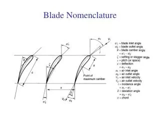
Blade Nomenclature
Blade Nomenclature. Blade Nomenclature. Compressor. Turbine. Blade 1. Last blade. Long. Short. Axial and Radial Flow Turbines. Differences between turbine and compressor:. Axial and Radial Flow Turbines. Differences between Radial and Axial Types . Axial Flow Turbines.

Blade Nomenclature
E N D
Presentation Transcript
Compressor Turbine Blade 1 Last blade Long Short Axial and Radial Flow Turbines Differences between turbine and compressor:
Axial and Radial Flow Turbines Differences between Radial and Axial Types.
Axial Flow Turbines Most of the gas turbines employ the axial flow turbines. The chapter is concerned with axial flow turbines. The radial turbine can handle low mass flows more efficiently than the axial flow machines.
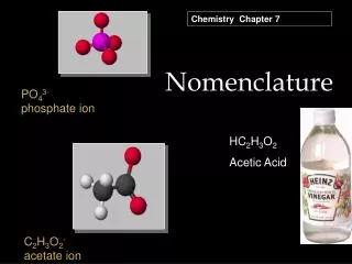
Axial Flow Turbine Elementary Theory of Axial Flow Turbine ► Velocity Triangles. ■ The velocity triangles for one axial flow turbine stage and the nomenclature employed are shown. The gas enters the row of nozzle blades with a static pressure and temperature P1, T1, and a velocity C1, is expanded to P2, T2, with an increased velocity C2 at an angle α2. ■ The rotor blade angle will be chosen to suit the direction β2 of the gas velocity V2 relative to the blade at inlet. ■ V2 and β2 are obtained from the velocity diagram of known C2, α2, and U.
Axial Flow Turbine • The gas leaves the rotor at β3, T3, with relative velocity V3 at an angle β3. • C3 and α3 can be obtained from the velocity diagram. • Elementary Theory
Axial Flow Turbine ► Single Stage Turbine ■ C1 is axial → α1 = 0, and C1 = Cα1. For similar stages (same black shapes) C1 = C3, and α1 = α3, called repeating stage. ■ Due to change of U with radius, velocity triangles vary from root to tip of the blade.
Axial Flow Turbine ► Assumptions ■ Consider conditions at the mean diameter of the annulus will represent the average picture of what happen to total mass flow. ■ This is valid for low ratio of tip radius to root radius. ■ For high radii ratio, 3-D effects have to be considered. ■ The change of tangential (whirl) mass is . This amount produces useful torque. ■ The change in axial component produces the axial thrust on the rotor. ■ Also there is an axial thrust due to P2 – P3. ■ These forces (net thrust on turbine rotor) are normally balanced by the thrust on the compressor rotor.
Axial Flow Turbine ► Calculation of Work Assume Ca= constant (1)
Axial Flow Turbine Applying principle of angular momentum From Equation (1) Steady-state energy equation: Thus:
Axial Flow Turbine Elementary theory of axial flow turbine
Axial Flow Turbine ηs is the isentropic stage efficiency based on stagnation (total) temperature. (used for land-based gas turbines). Defining ψ = blade loading coefficient (temperature drop coefficient)
Axial Flow Turbine Thus, Degree of reaction: 0 ≤ Λ ≤ 1 (a) For, Ca = const. and C3 = C1 and relative to rotor blades no work, thus
Axial Flow Turbine Substitute in (a):
Axial Flow Turbine Λ = 0.5 → Symm. velocity triangles ● Λ = 0 : Impulse turbine ● Λ = 1 : Defining flow coefficient:
Axial Flow Turbine Adding: From:
Axial Flow Turbine If , Λ, and are assumed, blade angles can be determined. ● For aircraft applications: 3 < ψ < s, 0.8 < < 1 ● For industrial applications: is less (more stages) is less (larger engine size) α3 < 20 (to min. losses in nozzle) ● Loss coefficient: Λ and Y: The proportion of the leaving energy which is degraded by friction.
Axial Flow Turbine Example (Mean diameter design) Given: Assumptions: Rotational speed fixed by compressor: N = 250 rps Mean blade speed: 340 m/s Nozzle loss coefficient:
Axial Flow Turbine • Calculation: • Λ degree of reaction at mean radius • Plot velocity diagrams • Blade height h, tip/root radius, Assume: The temperature drop coefficient: Assume (try):
Axial Flow Turbine * To calculate degree of reaction Λ: ■ Get β3: α3 = 0 ■ To get Λ use This is low as a mean radius value because Λ will be low or negative at the root. This introduce a value for α3. Take α3 = 10°
Axial Flow Turbine Reaction at root should be checked. Thus α3 = 10°, β3 = tan-1 1.426 = 54.96
Axial Flow Turbine With knowledge of plot velocity diagrams. * Determine blade height h and tip/root radius ratio, . Assumption: Calculation of area at Section 2 (exit of nozzle)
Axial Flow Turbine For the nozzle: P2 > Pc, the nozzle is not choked.
Axial Flow Turbine Calculate areas at section (1) inlet nozzle and (3) exit rotor.
Axial Flow Turbine Mean radius using areas at stations 1,2,3 thus
Axial Flow Turbine Blade with width W Normally taken as W=h/3 Spacing s between axial blades
Axial Flow Turbine Vortex Theory The blade speed ( u=r) changes from root to tip, thus velocity triangles must vary from root to tip. Free Vortex design axial velocity is constant over the annulus. Whirl velocity is inversely proportional to annulus. Along the radius.
Axial Flow Turbine For variable density, m is given by
Axial Flow Turbine Ex: Free vortex Results from mean diameter calculations