Download
1 / 60
720 likes | 1.2k Vues
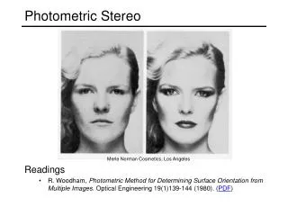
Radiometry and Photometric Stereo. Estimate the 3D shape from shading information. Can you tell the shape of an object from these photos ?. White-out: Snow and Overcast Skies. CAN’T perceive the shape of the snow covered terrain!. CAN perceive shape in regions

E N D
Estimate the 3D shape from shading information • Can you tell the shape of an object from these photos ?
White-out: Snow and Overcast Skies CAN’T perceive the shape of the snow covered terrain! CAN perceive shape in regions lit by the street lamp!! WHY?
Radiometry • What determines the brightness of an image pixel? Light sourceproperties Sensor characteristics Surface shape Exposure Surface reflectanceproperties Optics Slide by L. Fei-Fei
The journey of the light ray • Camera response function: the mapping f from irradiance to pixel values • Useful if we want to estimate material properties • Shape from shading requires irradiance • Enables us to create high dynamic range images Source: S. Seitz, P. Debevec
Recovering the camera response function • Method 1: Modeling • Carefully model every step in the pipeline • Measure aperture, model film, digitizer, etc. • This is really hard to get right Slide by Steve Seitz
Recovering the camera response function • Method 1: Modeling • Carefully model every step in the pipeline • Measure aperture, model film, digitizer, etc. • This is really hard to get right • Method 2: Calibration • Take pictures of several objects with known irradiance • Measure the pixel values • Fit a function pixel intensity = response curve irradiance Slide by Steve Seitz
Recovering the camera response function pixel intensity = response curve Exposure (log scale) irradiance * time = • Method 3: Multiple exposures • Consider taking images with shutter speeds 1/1000, 1/100, 1/10, 1 • The sensor exposures in consecutive images get scaled by a factor of 10 • This is the same as observing values of the response function for a range of irradiances:f(E), f(10E), f(100E), etc. • Can fit a function to these successive values • For more info • P. E. Debevec and J. Malik. Recovering High Dynamic Range Radiance Maps from Photographs. In SIGGRAPH 97, August 1997 Slide by Steve Seitz
The interaction of light and matter • What happens when a light ray hits a point on an object? • Some of the light gets absorbed • converted to other forms of energy (e.g., heat) • Some gets transmitted through the object • possibly bent, through “refraction” • Some gets reflected • possibly in multiple directions at once • Really complicated things can happen • fluorescence • Let’s consider the case of reflection in detail • In the most general case, a single incoming ray could be reflected in all directions. How can we describe the amount of light reflected in each direction? Slide by Steve Seitz
Bidirectional reflectance distribution function (BRDF) surface normal • Model of local reflection that tells how bright a surface appears when viewed from one direction when light falls on it from another • Definition: ratio of the radiance in the outgoing direction to irradiance in the incident direction • Radiance leaving a surface in a particular direction: add contributions from every incoming direction
Gonioreflectometers • Can add fourth degree of freedom to measure anisotropic BRDFs
Diffuse reflection • Dull, matte surfaces like chalk or latex paint • Microfacets scatter incoming light randomly • Light is reflected equally in all directions: BRDF is constant • Albedo: fraction of incident irradiance reflected by the surface • Radiosity: total power leaving the surface per unit area (regardless of direction)
Diffuse reflection: Lambert’s law • Viewed brightness does not depend on viewing direction, but it does depend on direction of illumination B: radiosity ρ: albedo N: unit normal S: source vector (magnitude proportional to intensity of the source) N S x
Specular reflection • Radiation arriving along a source direction leaves along the specular direction (source direction reflected about normal) • Some fraction is absorbed, some reflected • On real surfaces, energy usually goes into a lobe of directions • Phong model: reflected energy falls of with • Lambertian + specular model: sum of diffuse and specular term
Specular reflection Moving the light source Changing the exponent
Example Surfaces Surface Reflection: Specular Reflection Glossy Appearance Highlights Dominant for Metals Body Reflection: Diffuse Reflection Matte Appearance Non-Homogeneous Medium Clay, paper, etc Many materials exhibit both Reflections:
Diffuse Reflection and Lambertian BRDF source intensity I incident direction normal viewing direction surface element • Surface appears equally bright from ALL directions! (independent of ) albedo • Lambertian BRDF is simply a constant : • Surface Radiance : source intensity • Commonly used in Vision and Graphics!
Specular Reflection and Mirror BRDF source intensity I specular/mirror direction incident direction normal viewing direction surface element • Valid for very smooth surfaces. • All incident light energy reflected in a SINGLE direction (only when = ). • Mirror BRDF is simply a double-delta function : specular albedo • Surface Radiance :
Combing Specular and Diffuse: Dichromatic Reflection Observed Image Color = a x Body Color + b x Specular Reflection Color Klinker-Shafer-Kanade 1988 R Color of Source (Specular reflection) Does not specify any specific model for Diffuse/specular reflection G Color of Surface (Diffuse/Body Reflection) B
Diffuse and Specular Reflection diffuse specular diffuse+specular
Image Intensity and 3D Geometry • Shading as a cue for shape reconstruction • What is the relation between intensity and shape? • Reflectance Map
Equation of plane or Let Surface normal Surface Normal surface normal
Normal vector Source vector plane is called the Gradient Space (pq plane) • Every point on it corresponds to a particular surface orientation Gradient Space
Reflectance Map : source brightness : surface albedo (reflectance) : constant (optical system) Image irradiance: Let then • Relates image irradiance I(x,y) to surface orientation (p,q) for given source direction and surface reflectance • Lambertian case:
Reflectance Map Reflectance Map (Lambertian) Iso-brightness contour cone of constant • Lambertian case
Reflectance Map iso-brightness contour • Lambertian case Note: is maximum when
Reflectance Map Diffuse peak Specular peak • Glossy surfaces (Torrance-Sparrow reflectance model) diffuse term specular term
Shape from a Single Image? • Given a single image of an object with known surface reflectance taken under a known light source, can we recover the shape of the object? • Given R(p,q) ( (pS,qS) and surface reflectance) can we determine (p,q) uniquely for each image point? NO • Solution: Take more images • Photometric stereo
Photometric Stereo Lambertian case: Image irradiance: • We can write this in matrix form:
Solving the Equations inverse
More than Three Light Sources • Least squares solution: Moore-Penrose pseudo inverse • Solve for as before • Get better results by using more lights
Color Images • The case of RGB images • get three sets of equations, one per color channel: • Simple solution: first solve for using one channel • Then substitute known into above equations to get • Or combine three channels and solve for
Computing light source directions • Trick: place a chrome sphere in the scene • the location of the highlight tells you the source direction
Specular Reflection - Recap • For a perfect mirror, light is reflected about N • We see a highlight when • Then is given as follows:
Computing the Light Source Direction Chrome sphere that has a highlight at position h in the image • Can compute N by studying this figure • Hints: • use this equation: • can measure c, h, and r in the image N h H rN c C sphere in 3D image plane
Depth from Normals V2 V1 N • Get a similar equation for V2 • Each normal gives us two linear constraints on z • compute z values by solving a matrix equation
Limitations • Big problems • Doesn’t work for shiny things, semi-translucent things • Shadows, inter-reflections • Smaller problems • Camera and lights have to be distant • Calibration requirements • measure light source directions, intensities • camera response function
Trick for Handling Shadows • Weight each equation by the pixel brightness: • Gives weighted least-squares matrix equation: • Solve for as before
Results - Shape Shallow reconstruction (effect of interreflections) Accurate reconstruction (after removing interreflections)
Results - Albedo No Shading Information
Results • Estimate light source directions • Compute surface normals • Compute albedo values • Estimate depth from surface normals • Relight the object (with original texture and uniform albedo)
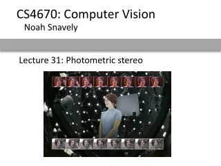
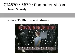
Photometric stereo example data from: http://www1.cs.columbia.edu/~belhumeur/pub/images/yalefacesB/readme
Alternative approach Reference object with same, but arbitrary, BRDF Use LUT to get from RGB1RGB2… vector to normal Hertzman and Seitz CVPR’03
Photometric stereo camera • A Hand-held Photometric Stereo Camera for 3-D Modeling, ICCV’09