Essential Functions of Plumbing Vents for Consistent Air Pressure
130 likes | 393 Vues
Learn the crucial role plumbing vents play in sewage systems: managing toxic gas, preventing siphoning, and maintaining air pressure. Follow vent sizing guidelines for optimal performance.

Essential Functions of Plumbing Vents for Consistent Air Pressure
E N D
Presentation Transcript
PLUMBING VENTS A vent is simply described as a device that can take unwanted air from one place and deposit it somewhere else, usually outside. A plumbing vent does two essential things. It provides an escape for toxic gas from a sewage system into the atmosphere. It also provides a channel for a source of air to replace effluent that moves through drain pipes, in order to replace the air displaced by the waste. In this manner, the air pressure within the waste system remains consistent, so the fluid that collects in the trap of a fixture is not sucked out by siphon action.
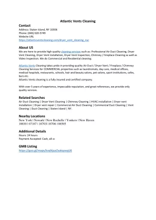
Notice in the vent size chart there are three things that must be known in order to select the proper size for a vent; Size of drain that serves the particular vent, Fixture Units served by the vent, and Length of vent
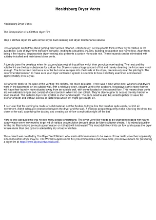
Notice in the elevation diagram of the plumbing group for the residence where the kitchen adjoins the bath room and utility room. Consider the vent that extends through the roof from the water closet. First, it serves all the fixtures, which equals 13 fixture units. The drain size that serves this vent is 3” The length of the vent is 12’ more or less. Go to the chart and find the first 3” drain at the left column, then move to the right and see that this particular one will serve only 10 fixture units. Since we have 13 fixture units, go to the next 3” drain below, and see that it will serve 30 fixture units. Since we have only 13 that line is OK. Then move to the right in the body of the chart and see the column under the 2” vent size and read the number 60. That means the 2” vent will serve the 13 fixture units with a 3” drain if the vent is not longer than 60 feet. So a 2” vent is proper for this application.
Consider the multistory diagram from your packet, page 40. Fixture unit values for fixtures in this diagram are taken from the top of page 43, “Design of Waste Drainage and Venting for a multistory assembly.” WC = 6 Urinal = 6 Lavatory = 1 Service Sink = 2 Floor drain = 1 The elevation is of a plumbing group back to back, so the fixtures in the diagram actually represent 2 fixtures back to back, attached to the drainage system.
Fixture unit values are shown as they accumulate down- ward. The dashed lines represent vents. Notice particularly the vent line that is adjacent to the main vertical drain – It is called a revent as a vertical drain cannot be used as a vent. 12 2 2 12 2 2 30 60 90 121