Reliability and Quality in Mission Critical Programming
70 likes | 344 Vues
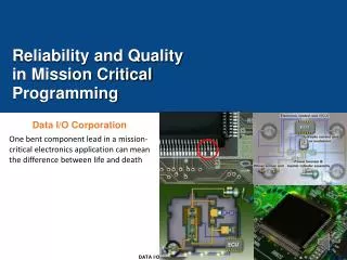
Reliability and Quality in Mission Critical Programming. Data I/O Corporation. One bent component lead in a mission-critical electronics application can mean the difference between life and death. Data I/O is the L eader in Quality Device Programming.

Reliability and Quality in Mission Critical Programming
E N D
Presentation Transcript
Reliability and Quality in Mission Critical Programming Data I/O Corporation One bent component lead in a mission-critical electronics application can meanthe difference between life and death
Data I/O is the Leader in Quality Device Programming • Data I/O is regarded as the highest quality programming equipment provider in the world, serving mission critical applications for over 40 years • Integrated Software for Traceability, Statistical analysis, Serialization and Version control • FlashCORE programming engine with universal device support • High insertion count sockets deliver the highest programming reliability and yields • Tested programming algorithms from deep and long term semiconductor relationships • 3D co-planarity checking to insure long term reliable operation Automotive manufacturers achieve the highest production yields and process efficiency using the Data I/O PS588 with its fully integrated 3D co-planarity vision system.
What is Coplanarity? • The term coplanarity is used to define the maximum distance between the physical contact points of a surface mount device (SMD) and the seating plane • When placed on a perfectly flat surface, the SMD will rest on the three lowest points, which defines the seating plane • The acceptable coplanarity specification defines the maximum gap that can exist between the seating plane and all other contacts on the device Coplanarity Deviation QFP Package Seating Plane
Why Coplanarity Matters • The bending of a lead severely damages the package and may affect the reliability. • The stress induced may result in microscopic cracks or chips in the package, and reduced adhesion, particularly where the lead enters. This reduces the ability of the package to resist ingress of moisture and may lead to failure through internal corrosion • Coplanarity ensures all device pins or balls are within their manufactured tolerances. This is critical at board assembly • Device pins are centered on pads prior to reflow • Proper solder flow ensures solid pin-to-pad bonding • Reduces the risk of solder fractures, cold solder joints and lifted pins • Proper device seating and bonding are best suiting to withstand heat and vibration • Coplanarity minimizes the risk of field failures, essential in mission critical applications such a automotive braking and missile guidance systems
Data I/O’s 3D Vision • PS588 with 3D vision can inspect a variety of leaded device packages including QFP, TSOP, SOIC and J-Lead devices in three dimensions. • Standard device file libraries provide for easy setup and training. • Custom telecentricoptics provide five views of the device in a single image which allows the software to calculate the 3D position of each lead. • Features • Easy Setup • Fast Inspection Times • Standard Part Library • PS 588 with 3D vision ensures the highest quality pin integrity • If you have a good, coplanar device with 16 leads and the first lead is bent up by 0.006 inches the coplanarity of it will become 0.006 inches and it should be rejected. • PS588 with 3D vision can see down to 7 microns of lead bending, which is 0.0003 inches
“Integrating 3D vision inspection with the programming process provides the highest production yield and process stability.” Thomas Koepp, Test Engineer, Johnson Controls
Questions to ask when evaluating automated programming equipment offering coplanarity What does your vision system measure? • 2D Vision measures device (length and width) • 3D Vision measures device (length, width, and depth) Data I/O’s PS588 with 3D vision measures X, Y and Z position of each device lead and calculates the deviations of each lead from the position that is defined in the device manufacturer’s part drawing. Does the vision system test co-planarity of each lead? PS588 3D vision has telecentricoptics providing five views of the device in a single image which allows the software to calculate the 3D position of each and every lead. How easy is the coplanaritysystem to use? PS588 3D vision includes standard device file libraries for easy setup and training Does the vision system easily manage changes in device height? PS588 3D vision has custom optics that automatically compensate for changes in device height to provide true metrology data.