Download
1 / 31
320 likes | 450 Vues
The Advanced Thin Ionization Calorimeter (ATIC) Long Duration Balloon Experiment.

E N D
The Advanced Thin Ionization Calorimeter (ATIC) Long Duration Balloon Experiment A ~1,660 kg experiment, carried to the near-space environment (~36 km) by a large volume (sufficient to fill a football stadium) helium filled balloon for 14 – 30 days over the continent of Antarctica, will measure the charge composition and energy spectra of primary cosmic rays over the energy range from about 1010 to 1014 eV in order to investigate the relationship between high energy galactic matter and remnant supernova shock waves. Louisiana State University, Marshall Space Flight Center, University of Maryland, Southern University, Moscow State University, Max Plank Institute for Solar System Research Project Initiation Conference 01/13/05
The ATIC Collaboration J.H. Adams2, H.S. Ahn3, G.L. Bashindzhagyan4, K.E. Batkov4, J. Chang6,7, M. Christl2, A.R. Fazely5, O. Ganel3R.M. Gunasingha5, T.G. Guzik1, J. Isbert1, K.C. Kim3, E.N. Kouznetsov4, M.I. Panasyuk4, A.D. Panov4, W.K.H. Schmidt6, E.S. Seo3, N.V. Sokolskaya4, J.P. Wefel1, J. Wu3, V.I. Zatsepin4 • Louisiana State University, Baton Rouge, LA, USA • Marshall Space Flight Center, Huntsville, AL, USA • University of Maryland, College Park, MD, USA • Skobeltsyn Institute of Nuclear Physics, Moscow State University, Russia • Southern University, Baton Rouge, LA, USA • Max Plank Institute for Solar System Research, Lindau, Germany • Purple Mountain Observatory, Chinese Academy of Sciences, China Project Initiation Conference 01/13/05
Standard Model of Cosmic Ray Acceleration • Supernova shock waves may accelerate cosmic rays via first order Fermi process • Model predicts an upper energy limit of E ~ Z x 1014 eV ATIC Energy Range Project Initiation Conference 01/13/05
ATIC Program Summary • Investigate relationship between Supernova Remnant (SNR) Shocks and high energy galactic cosmic rays (GCR) • Are SNR the “cosmic accelerators” for GCR • Measure GCR Hydrogen to Nickel from 50 GeV to ~100 TeV total energy • Determine spectral differences between elements • Flight test pixilated Silicon detector • Multiple flights needed to obtain necessary exposure • ATIC-1 test flight during 2000-2001 • ATIC-2 during 2002-2003 – 17 days exposure • ATIC-3 anticipated for 2005 • Scientific Ballooning programs at Universities provides unique education experiences for the future aerospace workforce • ATIC involved over 45 LSU & SU students Project Initiation Conference 01/13/05
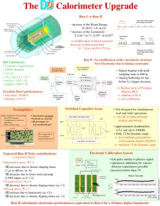
ATIC Instrument Summary • Ionization Calorimetry only practical method to measure high energy light elements • Silicon Matrix has 4,480 pixels to measure GCR charge in presence of shower backscatter • Plastic scintillator hodoscope, embedded in Carbon target, provides event trigger plus charge & trajectory information • Fully active calorimeter includes 320 Bismuth Germinate (BGO) crystals (400 BGO crystals for ATIC-3) to foster and measure the nuclear - electromagnetic cascade showers • Geometrical factor: 0.24 m2sr (S1 – S3 – BGO6) Project Initiation Conference 01/13/05
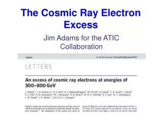
Preliminary Results Summary • Preliminary results from ATIC-1 and ATIC-2 • Fill gap between low energy AMS and high energy JACEE with accurate measurements • Preliminary indication that Hydrogen and Helium spectral indices are very similar • Measurements of Iron group show flattening of spectrum • Have measured GCR electrons up to about 2 TeV • At the highest energies, the heavy ion spectra show deviations, which might suggest that a modified Leaky Box Model, including a constant residual pathlength (0.13 g/cm2), is needed. Mg Fe O Ne Si C Preliminary charge histograms for E > 50 GeV from the ATIC-2 flight S S Ca Project Initiation Conference 01/13/05
All particle spectrum: ATIC, emulsion, and EAS data RUNJOB JACEE CASA-BLANCA Tibet KASKADE TUNKA ATIC-2 Project Initiation Conference 01/13/05
Energy spectra for H and He Project Initiation Conference 01/13/05
Energy spectra of abundant nuclei Mg C O/10 Si/10 Fe/100 Ne/100 HEAO-3-C2 ATIC-2 CRN Project Initiation Conference 01/13/05
ATIC also is able to identify CR electrons • High energy electrons provides addition information about the GCR source • Possible bump at 600 – 800 GeV seen by both Kobayashi and ATIC may be a source signature? e Project Initiation Conference 01/13/05
ATIC Instrument Details Si-Matrix: 4480 pixels each 2 cm x 1.5 cm mounted on offset ladders; 0.95 m x 1.05 m area; 16 bit ADC; CR-1 ASIC’s; sparsified readout. Scintillators: 3 x-y layers; 2 cm x 1 cm cross section; Bicron BC-408; Hamamatsu R5611 pmts both ends; two gain ranges; ACE ASIC. S1 – 336 channels; S2 – 280 channels; S3 – 192 channels; First level trigger: S1-S3 Calorimeter: 8 layers (10 for ATIC-3); 2.5 cm x 2.5 cm x 25 cm BGO crystals, 40 per layer, each crystal viewed by R5611 pmt; three gain ranges; ACE ASIC; 960 channels (1200 for ATIC-3). Data System: All data recorded on-board; 70 Gbyte disk (150 Gbyte for ATIC-3); LOS data rate – 330 kbps; TDRSS data rate – 4 kbps (6+ kbps for ATIC-3); Underflight capability (not used). Housekeeping: Temperature, Pressure, Voltage, Current, Rates, Software Status, Disk status Command Capability: Power on / off; Trigger type; Thresholds; Pre-scaler; Housekeeping frequency; LOS data rate, Reboot nodes; High Volt settings; Data collection on / off Geometry Factors: S1-S3: 0.42 m2sr; S1-S3-BGO 6: 0.24 m2sr; S1-S3-BGO 8: 0.21 m2sr Project Initiation Conference 01/13/05
Assembly of ATIC at Willy Attach the upper support structure Install Kelar pressure vessel shells Assemble / test detector stack and mount in lower support structure Solar arrays provide power & the payload is rolled out the hanger door Attach the thermal protection insulation ATIC is transported to the launch pad Project Initiation Conference 01/13/05
Flight and Recovery The good ATIC-1 landing on 1/13/01 (left) and the not so good landing of ATIC-2 on 1/18/03 (right) Flight path for ATIC-1 (2000) and ATIC-2 (2002) ATIC is designed to be disassembled in the field and recovered with Twin Otters. Two recovery flights are necessary to return all the ATIC components. Pictures show 1st recovery flight of ATIC-1 Project Initiation Conference 01/13/05
ATIC Test Flight from McMurdo • 43.5 Gbytes Recorded Data • 26,100,000 Cosmic Ray triggers • 1,300,000 Calibration records • 742,000 Housekeeping records • 18,300 Rate records • Low Energy Trigger > 10 GeV for protons • >70% Live-time • >90% of channels operating nominally • Internal pressure (~8 psi) held constant • Internal Temperature: 20 – 30 C • Altitude: 37 1.5 km • Launch: 12/28/00 04:25 UTC • Begin Science: 12/29/00 03:54 UTC • End Science: 01/12/01 20:33 UTC • Termination: 01/13/01 03:56 UTC • Recovery: 01/23/01; 01/25/01 Project Initiation Conference 01/13/05
First ATIC Science Flight from McMurdo • 65 Gbytes Recorded Data • 16,900,000 Cosmic Ray triggers • 1,600,000 Calibration records • 184,000 Housekeeping records • 26,000 Rate records • High Energy Trigger > 75 GeV for protons • >96% Live-time • >90% of channels operating nominally • Internal pressure (~8 psi) decreased slightly (~0.7 psi) for 1st 10 days then held constant • Internal Temperature: 12 – 22 C • Altitude: 36.5 1.5 km • Launch: 12/29/02 04:59 UTC • Begin Science: 12/30/02 05:40 UTC • End Science: 01/18/03 01:32 UTC • Termination: 01/18/03 02:01 UTC • Recovery: 01/28/03; 01/30/03 Project Initiation Conference 01/13/05
Preparation for ATIC-3 • Refurbish detectors Fall 2003 – Spring 2004 • Reconstruct missing structure (left on ice) Spring 2004 • Procure missing carbon target (left on ice) Spring 2004 • Reconstruct pressure vessel ring / flanges March – June 2004 • Leak & Proof pressure test vessel July 2004 • Assigned extra task by NASA to certify ATIC for 2004 July 17, 2004 • Arrive NSBF for Pre-deployment Integration August 19, 2004 • Complete Pre-deployment Integration Hang-Test September 16, 2004 • Receive stand-down for 2004 season from NASA October 20, 2004 • Directed to maintain ATIC in near flight ready status • Extra effort remains unreimbursed by NASA • Packed and ready to ship on 5 days notice • Instrument powered in shipping container for running preventative maintenance tests Project Initiation Conference 01/13/05
Pre-deployment Integration Hang Test • Assembled & tested instrument in ATIC-3 flight configuration • Added two layers to calorimeter • Flight configuration software loaded and tested • Integrated with NSBF SIP • VHF, TDRSS, Iridium • All uplink & downlink channels tested • Ground system assembled & tested • Through ROCC to flightline control • Though POCC to flightline & LSU control • Integrated & tested all NSBF equipment • Pointing rotator • NSBF solar arrays • Flight ladder, UTP • Obtained weight for fully assembled payload • Verified structural analysis for ATIC-3 configuration • Following test, disassembled payload and packed for shipment to McMurdo Project Initiation Conference 01/13/05
ATIC Weight Measurements ATIC-1 (2000) ATIC-2 (2002) ATIC-3 (2005) (493N) (515N) (NSBF 2004) Balloon 3701 lbs 3709 lbs 4050 lbs Science Gondola 3408 lbs 3386 lbs 3515 lbs Science Solar Array 64 lbs 64 lbs 80 lbs NSBF Electronics (SIP,etc.) 481 lbs 481 lbs 505 lbs NSBF Solar Array 140 lbs 128 lbs 150 lbs NASA Rotator 154 lbs 159 lbs 160 lbs Parachute & susp. 486 lbs 458 lbs 590 lbs Ballast 161 lbs 200 lbs 600 lbs Misc. (1 Ballast Hopper,etc.) 41 lbs 51 lbs 300 lbs Gross Load8636 lbs 8636 lbs 9950 lbs • Added two layers to the calorimeter for total of 10, otherwise no changes relative to ATIC-2 • Use 40M balloon for 2005 • Able to carry 600 lbs ballast Project Initiation Conference 01/13/05
ATIC Mechanical Certification • Initial ATIC Mechanical Report July 2000 • ATIC structure certified by NSBF August 2000 • Thermal analysis reviewed and approved August 2000 • Approval to fly Kevlar vessel at 8 psi November 2000 • Successful test flight (ATIC-1) Dec 2000 to Jan 2001 • Pressure Vessel Test (10 psi for 24 hrs.) May 2002 • Mechanical Report Update July 2002 • ATIC structure certified by NSBF August 2002 • Thermal analysis reviewed and approved August 2002 • Successful science flight (ATIC-2) Dec 2002 to Jan 2003 • Pressure Vessel Test (10 psi for 24 hrs.) July 2004 • Verified that original FEA was for 10 layer calorimeter July 2004 • Mechanical Report Update August 2004 • ATIC structure certified by NSBF September 2004 Project Initiation Conference 01/13/05
ATIC Data Rates • Exact data rate is trigger dependent • ATIC-2 high energy trigger resulted in an event rate of 550 to 700 per minute • Average event record size was ~2,200 bytes • Data rate was 200 kbps to 250 kbps • Other record types add ~10 kbps to this average data rate. • All data will be recorded on-board the instrument using a 150 Gbyte hard disk • Should be able to record all ATIC data for > 50 days • Downlink telemetry: • During line-of-sight (LOS) downlink data stream < 333 kilobits/s via auxiliary science transmitter • Downlink over TDRSS housekeeping, rates, high priority data, some calibration < 4-7 kilobits/s • Downlink compressed status information over Iridium via SIP < 29 bytes / min • Feasible to reduce average data rate to ~130 kbps and use High Gain TDRSS • Downlink >75% of data during flight & be less dependent upon recovery Project Initiation Conference 01/13/05
ATIC Commands • Discrete Commands • 10 discrete lines for power on/off control • 4 discrete lines for pressure control • Used only at launch, termination, and emergencies • Serial Commands • Simple protocol - Uplink cmd, downlink cmd ACK, execute cmd, downlink cmd status/return • All primitive cmds are 10 bytes long, so are encoded twice in each 20 byte cmd packet for error checking • Almost all uplinked cmds will be two bytes long and will execute a script of primitive cmds. • Command types • Software - Reboot node, Restart process, Start/stop LOS XMTR, etc. • Power - Power on/off subsystem, etc. • Detector - Calibrate BGO, Select trigger, etc. • Uplink Commands: • LOS for experiment check-out Þ max of 100 cmds / hr • All primitive cmds are 10 bytes long, so are encoded twice in each 20 byte cmd packet for error checking • During normal ops Þ max of 4 two byte cmds / hr • Problem diagnosis & resolution during LDB flight. • Require cmd rate > 4 cmds/hr • May require LOS link via airplane underflight Project Initiation Conference 01/13/05
ATIC Power System Flight Data System: 102 Watts - Flight Control Unit - Hard Disk Drives - Data Archive Unit - Detector Control Unit - Auxiliary Science Stack Detector Electronics: - Silicon Matrix (Fem's, Aclb's, Bias Supply ) 62 Watts - Plastic Scintillator (Fem's, Aclb's, Bias Supply ) 44 Watts - BGO Calorimeter (Fem's, Aclb's, Bias Supply )52 Watts Total Science Power: 260 Watts Thermal Control Heaters (Not needed during flight)200 Watts Total Power: 460 Watts Solar Array Max Output: ~580 Watts Project Initiation Conference 01/13/05
The ATIC Thermal Control System • Passive System: • pressure vessel containing internal science • 1.5 in fiberglass double-faced insulation blanket • outer facing: Atlas vps white laminate • inner facing: FSK aluminum • Absorptivity: 0.26 • Emissivity: 0.88 • Active System: • Internal resistance heaters (200W) • SIP platform external components: • battery (5 to 10W) and sci-stack (2W) insulated from deck • charge controller (10 to 20W) attached to deck as heatsink • insulation blanket over components Project Initiation Conference 01/13/05
ATIC Success Criteria • Project Success: • To meet science goals ATIC needs > 10 good H events at energies > 100 TeV • Minimum TOTAL exposure > 40 days with altitude above 110,000 feet • Implies multiple flights over multiple years • Minimum Success per Flight: • About 8 days with altitude above 110,000 feet with stability of 10,000 feet • Integrity of Aux Sci XTM data at 80% while in range • 90% of Silicon Matrix area, S1, S3 and BGO layers 2 through 8 are operational • Recovery of data from flight recorders • Recovery of all critical payload components • Photographs to assess structural damage • Desired Performance per Flight: • 14 days with altitude above 124,000 feet and stability of 5,000 feet • All detectors fully operational • Recovery of all data and entire payload • Two (or more) circumnavigations (~30 days) is HIGHLY desired • Reduce need for fourth flight • Now have two payloads as precedent (TIGER, CREAM) Project Initiation Conference 01/13/05
ATIC Launch Site Support • Workspace: • ~1000 square feet experiment setup and work area • 20 feet linear bench/table space for detector work • 20 feet linear bench/table/desk space for computers • 6 chairs • 3 ton overhead hoist with 20 feet clearance • Power: • One 220 V, 3 phase, 60 Hz, 6 Amp nominal • Two 120 V, single phase, 60 Hz, 15 Amp on UPS • Two 120 V, single phase, 60 Hz, 15 Amp • Gas: • 3 cylinders of dry Nitrogen • System to transfer gas to flight cylinders • Clean, dry, compressed air • Communication: • Telephone, Internet connection • Other: • Access to machine shop • Dedicated van for crew transport Project Initiation Conference 01/13/05
ATIC Flight Operations Support • Launch: • Electrical generator to power ATIC up to launch • Command & Data Interface: • Interface to ATIC Ground Data System at McMurdo • Interface to ATIC internet repeater at Palestine • Telemetry: • Line of sight used during experiment check-out tuning • Downlink 333 kbits/s via Aux. Sci. Transmitter • Uplink max of 100 cmds / hour • TDRSS and/or VHF for status & data • Max of 4 two byte cmds / hour • Flight Operations: • 24 x 7 monitoring of payload at ROCC and POCC • Underflight for emergency payload control (if needed) • Termination & Recovery: • Air support for termination, follow-down and chute cutaway • Air support for recovery of flight data disks and all critical payload components Project Initiation Conference 01/13/05
ATIC On-board Support • Orientation: • Rotator to keep PV arrays pointed to the sun • Telemetry: • Auxiliary science transmitter to downlink much of the ATIC data stream during LOS (333 kilobits/s, bi-phase encoded) • Will use TDRSS, VHF & Iridium • High Gain TDRSS is HIGHLY desired • 100 kbps would allow majority of data to be downlinked • Reduce need for full recovery • Commanding: • Discrete commands through Auxiliary Science Stack (about 14 cmds) • From ground through SIP to experiment • From underflight through SIP to experiment • From experiment to SIP (GPS position, altitude) • Field of View: • Minimum mass in field of view Project Initiation Conference 01/13/05
ATIC Shipping • Purchased C-container plus using a NSBF C-container to consolidate shipping. • Shipping now reduced to about eight crates: • Instrument C-Container (~5,600 lbs) • Electronics C-Container (~5,500 lbs) • Shell Crate (~2,300 lbs) • Solar Array Crate (334 lbs) • Battery Crate (260 lbs) • Solar Array Struts Crate (276 lbs) • Silicon Matrix Crate (440 lbs) • Si Matrix Electronic Crate (476 lbs) Project Initiation Conference 01/13/05
Anticipated ATIC Schedule January 13, 05 Project Initiation Conference Feb - July 05 Preventative Maintenance Testing July 05 Final packing for Antarctica August 2, 05 Ship ATIC to McMurdo ~October 1, 05 Late shipment (if necessary) October 28, 05 Setup crew arrives on flight line November, 05 Payload setup and testing November 10, 05 Silicon Matrix crew arrives ~November 27, 05 Partial crew change out ~December 1, 05 Calibrations / Testing with muons ~December 6, 05 Flight Ready ~January 4, 06 Partial crew change out ~February 3, 06 Instrument recovered, packed for shipment and remaining crew leaves Project Initiation Conference 01/13/05
Flight Operations Schedule Project Initiation Conference 01/13/05
Our enthusiastic crew is looking forward to working with NSF, RPSC and NSBF for another successful ATIC flight! link Project Initiation Conference 01/13/05