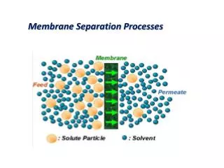
Membrane processes
Membrane processes. Membrane processes. Microfiltration Ultrafiltration Reverse osmosis Gas separation/permeation Pervaporation Dialysis Electrodialysis Liquid membranes Etc. Membrane applications in the pharmaceutical industry. UP water (RO) Nitrogen from air

Membrane processes
E N D
Presentation Transcript
Membrane processes Paul Ashall, 2007
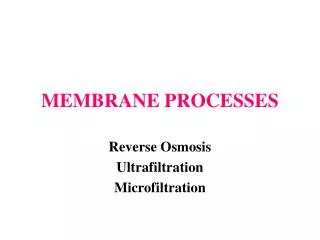
Membrane processes • Microfiltration • Ultrafiltration • Reverse osmosis • Gas separation/permeation • Pervaporation • Dialysis • Electrodialysis • Liquid membranes • Etc Paul Ashall, 2007
Membrane applications in the pharmaceutical industry • UP water (RO) • Nitrogen from air • Controlled drug delivery • Dehydration of solvents • Waste water treatment • Separation of isomers (e.g. naproxen) (‘Membrane Technology and Applications’ pp517, 518) • Membrane extraction • Sterile filtration Paul Ashall, 2007
Specific industrial applications Dialysis – hemodialysis (removal of waste metabolites, excess body water and restoration of electrolyte balance in blood) Microfiltration – sterilization of pharmaceuticals; purification of antibiotics;separation of mammalian cells from a liquid Ultrafiltration – recovery of vaccines and antibiotics from fermentation broth etc Ref. Seader p715 Paul Ashall, 2007
RETENTATE FEED PERMEATE Paul Ashall, 2007
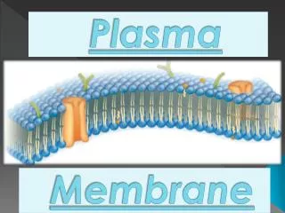
Membrane structure (dense, microporous, asymmetric, composite, membrane support) Paul Ashall, 2007
Membrane types - isotropic • Microporous – pores 0.01 to 10 microns diam.; separation of solutes is a function of molecular size and pore size distribution • Dense non-porous – driving force; diffusion; solubility • Electrically charged microporous Paul Ashall, 2007
Anisotropic (asymmetric) • Thin active surface layer supported on thicker porous layer • Composite – different polymers in layers • Others – ceramic, metal, liquid Paul Ashall, 2007
Asymmetric membranes Thin dense layer Microporous support Paul Ashall, 2007
Membrane materials • Polymers • Metal membranes • Ceramic membranes (metal oxide, carbon, glass) • Liquid membranes Paul Ashall, 2007
Membrane fabrication Isotropic • Solution casting • Melt extrusion • Track etch membranes (Baker fig. 3.4) • Expanded film membranes (Baker fig. 3.5) Paul Ashall, 2007
continued Anisotropic • Phase separation (Loeb – Sourirajan method) (see Baker fig. 3.12) • Interfacial polymerisation • Solution coated composite membranes • Plasma deposition Paul Ashall, 2007
Membrane modules • Plate and frame - flat sheets stacked into an element • Tubular (tubes) • Spiral wound designs using flat sheets • Hollow fibre - down to 40 microns diam. and possibly several metres long ; active layer on outside and a bundle with thousands of closely packed fibres is sealed in a cylinder Paul Ashall, 2007
Spiral wound module Paul Ashall, 2007
Membrane filtration – Buss-SMS-Canzler Paul Ashall, 2007
Operating considerations • Membrane fouling • Concentration polarisation (the layer of solution immediately adjacent to the membrane surface becomes depleted in the permeating solute on the feed side of the membrane and enriched in this component on the permeate side, which reduces the permeating components concentration difference across the membrane, thereby lowering the flux and the membrane selectivity) • Flow mode (cross flow, co-flow, counter flow) Paul Ashall, 2007
Aspects • Crossflow (as opposed to ‘dead end’) – cross flow velocity is an important operating parameter • Sub-micron particles • Thermodynamic driving force (P, T, c etc) for transport through membrane is activity gradient in membrane • Flux (kg m-2 h-1) • Selectivity • Membrane area Paul Ashall, 2007
Characteristics of filtration processes Paul Ashall, 2007
Models • Ficks law (solution-diffusion model) Free volume elements (pores) are spaces between polymer chains caused by thermal motion of polymer molecules. • Darcys law (pore flow model) Pores are large and fixed and connected. Paul Ashall, 2007
Simple model (liquid flow through a pore using Poiseuilles law) J = Δp ε d2 32 μ l J = flux l = pore length d = pore diam. Δp =pressure difference across pore μ = liquid viscosity ε = porosity (π d2 N/4, where N is number of pores per cm2) J/Δp – permeance Typical pore diameter: MF – 1micron; UF – 0.01 micron Paul Ashall, 2007
Mechanisms for transport through membranes • Bulk flow • Diffusion • Solution-diffusion (dense membranes – RO, PV, gas permeation) Paul Ashall, 2007
continued • Dense membranes: transport by a solution-diffusion mechanism • Microporous membranes: pores interconnected Paul Ashall, 2007
Separation of liquids • Porous membranes • Asymmetric membranes/dense polymer membranes Paul Ashall, 2007
continued • With porous membranes separation may depend just on differences in diffusivity. • With dense membranes permeation of liquids occurs by a solution-diffusion mechanism. Selectivity depends on the solubility ratio as well as the diffusivity ratio and these ratios are dependent on the chemical structure of the polymer and the liquids. The driving force for transport is the activity gradient in the membrane, but in contrast to gas separation, the driving force cannot be changed over a wide range by increasing the upstream pressure, since pressure has little effect on activity in the liquid phase. Paul Ashall, 2007
Microporous membranes • Porosity (ε) • Tortuosity (τ) (measure of path length compared to pore diameter) • Pore diameter (d) Ref. Baker p68 – Fig 2.30 Paul Ashall, 2007
Microporous membranes • Screen filters (see Baker fig. 2.31) – separation of particles at membrane surface. • Depth filters (see Baker fig. 2.34) – separation of particles in interior of the membrane by a capture mechanism; mechanisms are sieving and adsorption (inertial capture, Brownian diffusion, electrostatic adsorption) Ref. Baker pp69, 73 Paul Ashall, 2007
Filtration • Microfiltration (bacteria – potable water, 0.5 – 5 microns). Pore size specified. • Ultrafiltration (macromolecules, molecular mass 1000 – 106, 0.5 – 10-3 microns). Cut-off mol. wt. specified. • Nanofiltration (low molecular weight, non-volatile organics from water e.g. sugars). Cut off mol. wt. specified. • Reverse osmosis (salts) Paul Ashall, 2007
continued Crossflow operation (as opposed to ‘dead end’ filtration) Paul Ashall, 2007
Membrane types • Dense • High porosity • Narrow pore size distribution Paul Ashall, 2007
Ultrafiltration(UF) Uses a finely porous membrane to separate water and microsolutes from macromolecules and colloids. Membrane pore diameter 0.001 – 0.1 μm. Nominal ‘cut off’ molecular weight rating assigned to membrane. Membrane performance affected by: • Concentration polarisation • Membrane fouling • Membrane cleaning • Operating pressure Paul Ashall, 2007
Spiral wound UF module Paul Ashall, 2007
UF Membrane materials (Loeb- Sourirajan process) • Polyacrylonitrile (PAN) • PVC/PAN copolymers • Polysulphone • PVDF (polyvinylidene difluoride) • PES (polyethersulfone) • Cellulose acetate (CA) Paul Ashall, 2007
UF Modules • Tubular • Plate and frame • Spiral wound • Capillary hollow fibre Paul Ashall, 2007
UF applications • Protein concentration Paul Ashall, 2007
Microfiltration (MF) Porous membrane; particle diameter 0.1 – 10 μm Microfiltration lies between UF and conventional filtration. In-line or crossflow operation. Screen filters/depth filters (see Baker fig. 7.3, p 279) Challenge tests developed for pore diameter and pore size. Paul Ashall, 2007
MF Membrane materials • Cellulose acetate/cellulose nitrate • PAN – PVC • PVDF • PS Paul Ashall, 2007
MF Modules • Plate and frame • Cartridge filters (see Baker figs. 7.11/7.13, p288, 290) Paul Ashall, 2007
MF operation • Fouling • Backflushing • Constant flux operation Paul Ashall, 2007
MF uses • Sterile filtration of pharmaceuticals (0.22 μm rated filter) • Drinking water treatment Paul Ashall, 2007
Reverse osmosis Miscible solutions of different concentration separated by a membrane that is permeable to solvent but impermeable to solute. Diffusion of solvent occurs from less concentrated to a more concentrated solution where solvent activity is lower (osmosis). Osmotic pressure is pressure required to equalise solvent activities. If P > osmotic pressure is applied to more concentrated solution, solvent will diffuse from concentrated solution to dilute solution through membrane (reverse osmosis). Paul Ashall, 2007
Reverse osmosis The permeate is nearly pure water at ~ 1atm. and very high pressure is applied to the feed solution to make the activity of the water slightly greater than that in the permeate. This provides an activity gradient across the membrane even though the concentration of water in the product is higher than that in the feed. Paul Ashall, 2007
Reverse osmosis Permeate is pure water at 1 atm. and room temperature and feed solution is at high P. No phase change. Polymeric membranes used e.g. cellulose acetate 20 – 50 atm. operating pressure. Concentration polarisation at membrane surface. Paul Ashall, 2007
RO F P1 P2 P R P1 » P2 Paul Ashall, 2007
Model • Flux equations • Salt rejection coefficient Paul Ashall, 2007
Water flux Jw = cwDwvw (ΔP – Δπ) RT z Dw is diffusivity in membrane, cm2 s-1 cw is average water conc. in membrane, g cm-3 (~ 0.2) vw is partial molar volume of water, cm3g-1 ΔP pressure difference R gas constant T temperature Δπ osmotic pressure z membrane thickness Paul Ashall, 2007
Salt flux Js = Ds Ss (Δcs) z Ds diffusivity Ss solubility coefficient Δcs difference in solution concentration Ref. Baker pp 34, 195 Paul Ashall, 2007
Jw increases with ΔP and selectivity increases also since Js does not depend on ΔP. Paul Ashall, 2007
Membrane materials • Asymmetric cellulose acetate • Polyamides • Sulphonated polysulphones • Substituted PVA • Interfacial composite membranes • Composite membranes • Nanofiltration membranes (lower pressure, lower rejection; used for lower feed solution concentrations) Ref. Baker p203 Paul Ashall, 2007