Download
1 / 23
230 likes | 238 Vues
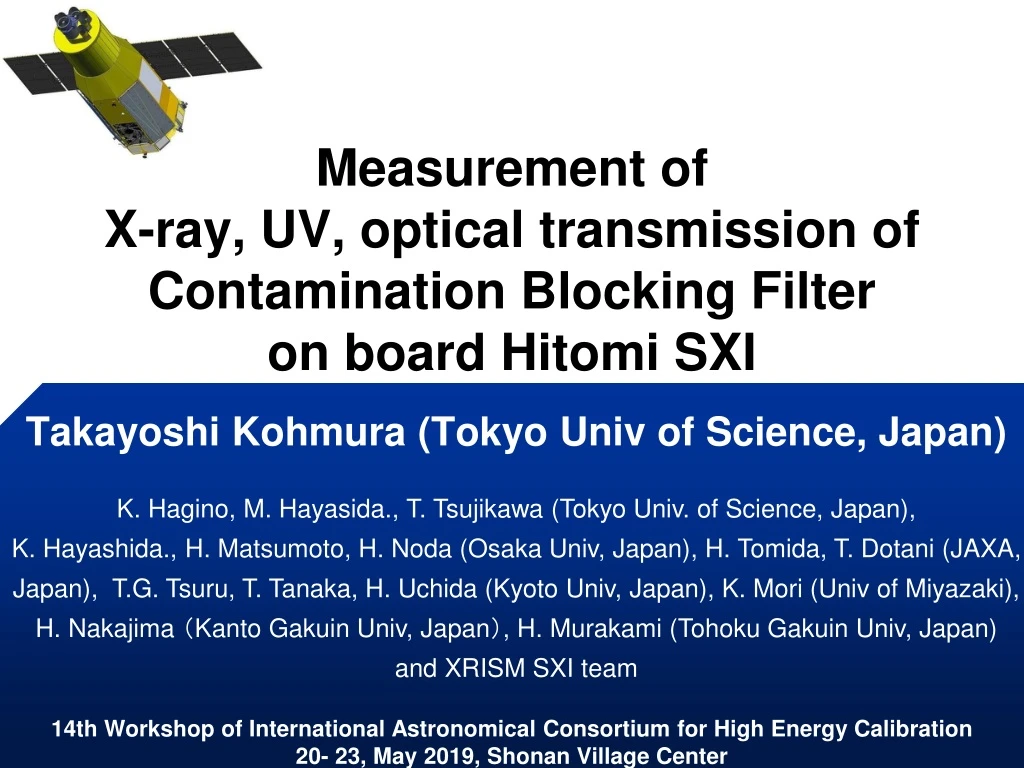
Measurement of X-ray, UV, optical transmission of Contamination Blocking Filter on board Hitomi SXI. Takayoshi Kohmura (Tokyo Univ of Science, Japan).

E N D
Measurement of X-ray, UV, optical transmission of Contamination Blocking Filter on board Hitomi SXI Takayoshi Kohmura (Tokyo Univ of Science, Japan) K. Hagino, M. Hayasida., T. Tsujikawa (Tokyo Univ. of Science, Japan), K. Hayashida., H. Matsumoto, H. Noda (Osaka Univ, Japan), H. Tomida, T. Dotani (JAXA, Japan), T.G. Tsuru, T. Tanaka, H. Uchida (Kyoto Univ, Japan), K. Mori (Univ of Miyazaki), H. Nakajima (Kanto Gakuin Univ, Japan), H. Murakami (Tohoku Gakuin Univ, Japan) and XRISM SXI team
Outline of this talk Hitomi SXI Contamination Blocking Filter ( CBF ) Optical transmission of CBF X-ray and UV transmission of CBF Discussion Conclusion
1. Hitomi SXI Mounted on the cold plate ① ② コンタミ 防止膜 フード ヒーター ~30cm ③ ④ 31mm 13cm ~72cm 31mm ~28cm • P-channel CCD manufactured by Hamamatsu Photonics • BI with depletion layer of 200mm • 24mm square pixel • ~62mm x 62mm しきり板 ベントパイプ 電子回路 基板
NeIX OVIII NeX MgXI OVII 2005-08-13 2005-08-31 2005-12-16 2006-01-17 2006-02-02 2. Contamination Blocking Filter • From our Suzaku XIS experiment in space, we noticed the degradation of QE due to the contamination of material in the satellite.
2. Contamination Blocking Filter コンタミ 防止膜 フード 13cm ~72cm ~28cm しきり板 CBF(Contamination Blocking Filter) was made by Luxel CLDT Al ; 80nm and 40nm Polyimide ; 200nm ベントパイプ 電子回路 基板
2. Contamination Blocking Filter 【 EUV shielding 】 • CBF: Contamination Blocking Filter • Pre-FM ( before 2015 ) • 200nm thick Polyimidewas covered with 30nm thick Al layers. 【 Optical Blocking 】 • OBL:Optical BlockingLayer • 100nm thick Alis directly coated over the BI-CCD wafer manufactured by Hamamatsu. Al(100nm) BI-CCD wafer Figure. Schematic view of OBL
2. Contamination Blocking Filter Optical transmission of OBL 10-4 ― Al 90nm ― Al 100nm (design value) ― Al 110nm 10-5 Transmission 10-6 10-7 10-8 200 400 600 800 1000 Optical wave length (nm) • We found the optical transmission was < ~10-5which was equivalent value that we had expected from the design thickness of OBL.
2. Contamination Blocking Filter Pinholes in Al Coating of OBL for Hitomi Satellite 2013/04/08 2014/09/03 • We had checked the pin holes on OBL by irradiating the optical light. • But, the number of pin holes was increasing during five months. • We decided to make the thickness of CBF thicker to block the optical light.
2. Contamination Blocking Filter FM-CBF (after 2015) Frame Mesh Al(80nm) Polyimide(100nm) CBF Al(40nm) • CBF was supported by the mesh with guard to block solar X-ray scattered middle plate in the satellite. • The thickness of mesh was 0.3mm, and its interval and width of mesh was 3mm and 0.15mm, respectively. • This guard did not cut the field of view of SXI.
3. Optical Transmission of CBF pre FM-CBF FM-CBF • We confirmed the optical transmission was <~5x10⁻⁵ which was expected from design thickness of new CBF.
4. X-ray and UV Transmission of CBF • We measured Soft X-ray and UV transmission of FM-CBF at the synchrotron facility in Japan (KEK Photon Factory). Vacuum Chamber Vacuum Chamber X-ray beam UV beam X-ray beam Vacuum Chamber Fig:BL-11B (1730-5000eV) Fig:BL-20A (20-60eV) Fig:BL-11A (150-1800eV) We measured the X-ray (UV) flux using photo diode with/without CBF, and calculated the X-ray (UV) transmission of CBF derived from the flux ratio between two them.
4. X-ray and UV Transmission of CBF Experimental Set up Witness Filter CBF Folder X-ray / UV Beam ~10mm New FM-CBFs Old FM-CBF CBF folder ~120mm Photo Diode
4. X-ray and UV Transmission of CBF BL-11A pre FM-CBF FM-CBF • The X-ray transmission of new FM CBF was lower than old CBF by ~10% at O-K due to the thicker Al. • The X-ray energy was calibrated using absorption edges of old FM-CBF as a reference.
4. X-ray and UV Transmission of CBF BL-11A C-K N-K O-K Al-K
4. X-ray and UV Transmission of CBF BL-11A+BL11B Transmission (%)
4. X-ray and UV Transmission of CBF BL-20A 1 Old FM-CBF New FM-CBF Transmission (%) 0.1 0.01 The UV transmission of new FM CBFs was same as its old ones because the thickness of polyimide was not changed.
4.Discussion BL-11A without Al2O3 with Al2O3 The thickness of polyimide and Al were slightly thicker and thinner value than their reported from Luxel Co LTD.
4.Discussion BL-11A + BL-11B Transmission (%)
4.Discussion ー measured trasmission ー calculated value based on thickness of CBF by Luxel ー calculated value based on thickness derived by our X-ray transmission measurement • The optical transmission was higher than what we expected from Al thickness reported from Luxel Co LTD. • The thickness Al was thinner which we derived from both X-ray and optical transmission measurement.
5. Conclusion • We remanufactured Contamination Blocking Filter of SXI due to the increase in the number of the pin holes on the OBL. • We measured the optical, soft X-ray, and UV transmission of FM-CBF for Hitomi SXI. • The optical transmission of FM-CBF were lower than 5x10⁻⁵. This result meets the requirement of optical shield of SXI, but slightly higher than we expected from Luxel design thickness. • The X-ray transmission was also measured precisely including XAFS structure around C, N, O and Al absorption edges, and this results also suggests the thinner Al thickness which predicted the optical transmission. • We also measured the UV transmission and confirmed the low transmission in order to block the 304A UV light from sunlit atmosphere. • We will adopt CBF for XRISM SXI of the same design as FM-CBF Hitomi SXI.
EUV In order to observe X-ray in space,we have to block this EUV light from Sunlit atmosphere as well as the optical light from objects. Sun @ 304Å observed with SOHO satellite The north pole image of the earth @304Å north pole
3. Optical Transmission of CBF Vacuum Chamber Optical light source and Grating spectrometer 450nm~950nm Al filter Reducer of the optical light OptilcaLight (OP) OP OP • We measured the optical flux using photo diode with/without CBF, and calculated the optical transmission of CBF derived from the flux ratio between two them.