Linear Collider vertex detector technology options
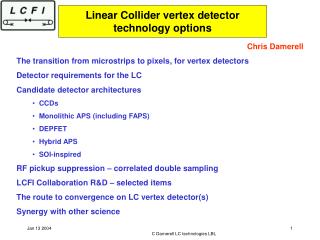
Linear Collider vertex detector technology options. Chris Damerell The transition from microstrips to pixels, for vertex detectors Detector requirements for the LC Candidate detector architectures CCDs Monolithic APS (including FAPS) DEPFET Hybrid APS SOI-inspired

Linear Collider vertex detector technology options
E N D
Presentation Transcript
Linear Collider vertex detector technology options • Chris Damerell • The transition from microstrips to pixels, for vertex detectors • Detector requirements for the LC • Candidate detector architectures • CCDs • Monolithic APS (including FAPS) • DEPFET • Hybrid APS • SOI-inspired • RF pickup suppression – correlated double sampling • LCFI Collaboration R&D – selected items • The route to convergence on LC vertex detector(s) • Synergy with other science C Damerell LC technologies LBL
Since late’70s, successful vertex detectors (for heavy flavour tagging) were mainly based on silicon microstrips • Interesting technology shift is under way. Within 5 years, will mostly be based on silicon pixels • Why is this? • highest performance b and charm reconstruction in dense track environments has come from two pixel-based detectors, NA32 in ’80s, SLD in ’90s • extreme radiation environments in the inferno close to IP at future hadron colliders • high backgrounds, and high track density in core of jets at future e+e- colliders • These disparate requirements at hadron and e+e- colliders have very different solutions (both of them pixel-based), and are supported by contrasting R&D programmes • This transition to pixels implies synergies with other areas of science, where images taken with IR, visible, UV, X-rays benefit from the technologies being developed for HEP vertex detectors, and vice versa C Damerell LC technologies LBL
Of course, it will definitely be silicon pixels at the LC, or will it? C Damerell LC technologies LBL
Detector requirements • 5 layers, inner layer at radius 12-15 mm • 3-hit coverage to cosq = 0.96 • thin layers (<0.1% X0 ) for minimal multiple scattering and g conversions C Damerell LC technologies LBL
silicon pixels of size ~ 20 mm square for low cluster-merging in jets • support structure with micron precision/stability (specially important for oblique tracks near ladder ends) • on-detector signal processing, so almost no external connections • power dissipation measured in few tens of watts, so gas cooling is sufficient (this is vital for low material budget) • ‘adequate’ radiation hardness (tens of krads from pair bgd, plus few times 109 neutrons/cm2/yr) • readout time ~ 5 ms for JLC/NLC (between bunch trains) • ~ 50 ms for TESLA (20 frames/bunch train) • low mult. scatt term important for efficient charm ID and B vertex charge; quantitative physics examples are now being studied … C Damerell LC technologies LBL
The ‘good enough’ vertex detector has yet to be built • Collider vertex detectors have often restricted the capability of their experiments for leading edge physics: • the possible top signal at 40 GeV in UA1 (early ’80s) • the possible Higgs signal in LEP • Bs signal in SLD [NOT considered when SLD was being designed!] • Match to LC physics needs cannot be taken for granted • Rbp could strike again … • Intensive R&D in several technologies will surely be justified (cost effective) in terms of LC physics reach • The LC does offer a potential technical advantage (hence enhanced physics reach) wrt the inferno at the heart of LHC C Damerell LC technologies LBL
The SLD experience … C Damerell LC technologies LBL
Candidate detector architectures C Damerell LC technologies LBL
MAPS • ‘Standard CMOS process’: signal charge is collected onto gate of front-end transistor from undepleted bulk or epitaxial layer • However this isn’t obligatory – early developments by Sherwood Parker et al, with 300 µm fully depleted devices were highly successful • First results from Strasbourg group were also based on few mm2 devices and minimal in-pixel logic • Recently, using 0.35 µm CMOS, increasing functionality is being implemented at the periphery of the chip • Due to limited gm of in-pixel transistors (?) 50 µs readout time requires ‘sideways’ column architecture – MAPS(2) • Flexible active pixel idea (Renato Turchetta at RAL) could be a more favourable architecture for TESLA – MAPS(1) C Damerell LC technologies LBL
DEPFET • Based on detector-grade high resistivity silicon, fully depleted • Requirement of supporting CMOS chips on 2 sides may be a significant limitation • HAPS (incl new SoI-inspired) • Read 1 in N pixels, by analogy with capacitive charge division in strip detectors • Spatial resolution tends to be somewhat unstable • Implications for 2-track resolution? • SoI approach could reduce material, but looks pretty complex (?) C Damerell LC technologies LBL
MIMOSA-5 Strasbourg group C Damerell LC technologies LBL
FAPS: RAL group • FAPS could be extended to a full 20 samples per train, stored in pixel • If this doesn’t fit with 0.25 mm CMOS, will surely be OK with 0.13 mm • Idea is to relax the requirement for fast, precise, signal transmission to chip periphery during train, and so render long columns feasible, with all processing logic outside the detector active volume, as for the CCD architecture • Test devices implemented using a 0.25 mm process – TSMC(imaging) C Damerell LC technologies LBL
DEPFET Bonn/Munich group MOS transistor instead of JFET A pixel size of ca. 20 x 20 µm² is achievable using 3µm minimum feature size. C Damerell LC technologies LBL
matrix is read out row-wise first thinned samples: • thin detector-area • down to 50µm • frame for mechanical • stability carries readout- • and steering-chips [L.Andricek, MPI Munich] C Damerell LC technologies LBL
DEPFET pixel matrix Low power consumption Fast random access to specific array regions • Read filled cells of a row • Clear the internal gates • of the row • - Read empty cells C Damerell LC technologies LBL
Polyresistor Interleaved pixel Readout pixel readout pitch = n x pixel pitch Small enough for an effective sampling Large enough to house the VLSI front-end cell p + n Hybrid Pixel Detector with Interleaved Pixels HAPS Insubria/Krakow group Charge carriers generated underneath one ofthe interleaved pixel cells induce a signal on the capacitively coupled read-out pixels, leading to a spatial accuracy improvement by a proper signal interpolation. C Damerell LC technologies LBL
Resolution: Interleaved pixels (efficient charge sharing): 3 m function Average resolution Resolution vs. spot position Charge Sharing Studies – Resolution • parameterization allows a coordinate reconstruction and resolution measurement C Damerell LC technologies LBL
Detector handlable wafer High resistivity 300 m thick Electronics active layer Low resistivity 1.5 m thick Readout pixels (min charge sharing): 10 m SOI detector Insubria/Krakow group Detector:conventional p+-n, DC-coupled Electronics:preliminary solution – conventional bulk MOS technology on the thick SOI substrate C Damerell LC technologies LBL
RF pickup suppression • Beam-associated RF radiation penetrating the beam-pipe (even 0.5 mm Be) appears to be negligible • However, flanges, BPM cables, etc can permit RF radiation to leak out • SLD experience: • analogue signals stored securely in CCD buried channel • Digital logic (PLL in optical links) was disrupted – fortunately could be restored within some tens of ms of collisions) • NLC/JLC: • could envisage similar settling/restoration before readout • TESLA: • need to read detector repeatedly during train, to internal storage of sparsified data • each internal frame readout spans ~150 BX, so electronics is hit repeatedly by whatever RF is present • For SLD VTX, this would have been fatal C Damerell LC technologies LBL
The problem: 109 signals being read in an electrically hyperactive environment • could produce a data deluge • contrast between two different collider options and at least 5 detector options • Discussion points: • Reality check: 300 Mpixels at SLD • CCD-based detector at NLC (natural evolution) • CCD-based detector at TESLA • Other detector technologies at NLC/TESLA C Damerell LC technologies LBL
Column Parallel CCD Readout time = N/Fout M N N “Classic CCD” Readout time NM/Fout CCD signal storage and sensing: C Damerell LC technologies LBL
Signal charge from MIP stored safely in buried channel of device • During readout, charge is transferred to output node • Classical Correlated Double Sampling (CDS): • RESET/READ 1/TRANSFER/READ 2 (originally to suppress reset noise) • Sparse data scenario permits faster (but equivalent) noise suppression: • RESET/READ 1/TRANSFER/READ 2/TRANSFER/READ 3/ … C Damerell LC technologies LBL
In addition, Extended Row Filter (ERF) can suppress pickup: C Damerell LC technologies LBL
SLD experience: Without ERF, rate of trigger pixels would have deluged the DAQ system Readout at 5 MHz, during ‘quiet’ inter-bunch periods of 8 ms duration C Damerell LC technologies LBL
For NLC, substitute bunch train for bunch • Otherwise, as at SLD, and expect same strategy to work • Can again wait many ms for beam-related pickup to die away • CPCCD lends itself to required functionality in readout chip C Damerell LC technologies LBL
For TESLA, one enters uncharted waters • Must read during most of 337 ns between bunches (17 samples at 50 MHz in CPCCD) • Could cut to say 14 samples giving ~ 50 ns settling time. Will this suffice? What will be the noise penalty due to pickup between samples N and N+1? C Damerell LC technologies LBL
DEPFET pixel • DEPFET enjoys same strengths as CCD regarding CDS • However, ERF would slow down the readout correspondingly • [N samples before and after RESET would imply N-fold increase in readout time] C Damerell LC technologies LBL
Basic MAPS architecture at TESLA • ‘Transverse’ readout to satisfy the 50 ms requirement • SAMPLE/RESET at 50 ms intervals • Will be OK for reset noise, but could be catastrophic for pickup from intervening 150 BXs • Possible way out: Could do SAMPLE/RESET/SAMPLE within one BX, at 50 ms intervals • This would strongly suppress pickup while sacrificing the suppression of reset noise. Tolerable for CNODE < approx 10 fF • Could also (at expense of readout time) implement CCD-like ERF if required C Damerell LC technologies LBL
FAPS or FAPS(CAP) concept: Renato Turchetta • Flexible APS permits storage of 20 samples during train • Readout of above-threshold pixel hits and their neighbours proceeds at leisure in the 200 ms between trains • This will permit ‘longitudinal’ readout, with benefit to material budget • However, CDS options are no different than for MAPS C Damerell LC technologies LBL
New concept: FAPS(CCD) • MIPs which hit the storage register (<10% area) leave a small spurious signal – easily handled by software • Lessons being learned about CCDs with reduced clock amplitude (eg without barrier implants) will feed directly into this design concept • Increasing availability of mixed CCD/CMOS technology at a few foundries including Sarnoff in USA C Damerell LC technologies LBL
Column-pair readout of sparse data (analogue signals to ADCs at ends of ladder) • Manufacturability would require not only mixed technology, but also large area precise stitching, etc • Could provide the ultimate in pickup immunity, but will this be necessary? C Damerell LC technologies LBL
CONCLUSIONS (on pickup) • Pace of development of silicon pixel devices {CCD, MAPS, FAPS(CAP), FAPS(CCD), DEPFET, SOI, HAPS, …} is breathtaking • High level of pickup immunity can surely be engineered into some or all of these architectures • If at end of this year, we have a warm machine, we can relax and focus mainly on other criteria • If TESLA, suggest producing a serious BDS mockup to simulate pickup effects • In either case, expect surprises from 109 pixels in the LC environment, so it’s probably wise to back contrasting technologies for the (assumed) two detectors, in order to spread the risk • At SLD, we were lucky in being able to retro-fit the ERF. Inadvisable to assume this luck will hold, in the unknown territory to be explored next time … C Damerell LC technologies LBL
LCFI R&D programme Novel CCDs and readout electronics • CCD sizes similar to SLD, but readout needs to be 20-2000 times faster • Eliminate bulky electronics which would degrade fwd tracking and calorimetry • Total of 800 Mpixels, cf 307 Mpixels for SLD • TESLA readout requirement stimulated concept of ‘column parallel’ operation • This implies an innovative CCD/CMOS hybrid. If successful, this architecture may also be preferred for NLC/JLC. However, for this case, the conventional architecture with a multi-output linear register may suffice C Damerell LC technologies LBL
Column Parallel CCD Readout time = N/Fout M N N “Classic CCD” Readout time NM/Fout • CPCCD has max possible readout speed, for given noise performance • Readout IC (amp+ADC on 20 mm pitch) only became available with deep submicron CMOS technology • TESLA requires parallel register clocking at 50 MHz: 1 MHz is fine for NLC C Damerell LC technologies LBL
electronics only at the ends of the ladders • bump-bonded assembly between thinned CPCCD and DSM readout chip • readout chip does all the signal processing, yielding sparsified digital data • CPCCD is driven with high frequency, low voltage clocks (currently 2 V, goal around 1 V peak-peak) • low inductance layout is required for clock delivery C Damerell LC technologies LBL
Standard 2-phase implant Field-enhanced 2-phase implant (high speed) Metallised gates (high speed) Metallised gates (high speed) 2-stage source followers Source followers Source followers Direct Direct Readout ASIC Readout ASIC To pre-amps Features of our first CPCCD: • 2 different charge transfer regions • 3 types of output circuitry • Independent CPCCD and readout chip testing possible: • without readout chip - use external wire bonded electronics • without bump bonding - use wire bonds to readout chip • finally, bump-bonded • Different readout concepts can be tested (direct charge sensing, and voltage sensing via source follower) C Damerell LC technologies LBL
CPC-1 fully tested standalone, wire-bonded assembly now under test Direct connections and 2-stage source followers 1-stage source followers and direct connections on 20 μm pitch C Damerell LC technologies LBL
Single pixel events seen in one column of CPC-1 with 2 V peak-peak clocks C Damerell LC technologies LBL
Wire/bump bond pads Voltage Amplifiers Charge Amplifiers 250 5-bit flash ADCs FIFO Wire/bump bond pads C Damerell LC technologies LBL
CPR-1 fully tested standalone C Damerell LC technologies LBL
LCFI R&DThinnest possible detector layers • 3 approaches • Unsupported silicon • Semi-supported silicon • Supported silicon • Unsupported approach attractive – ‘like wires in a drift chamber’ • Works beautifully along ladder length (sagitta stability around 2 microns) • However, processed thin CCD is not like a wire: it’s an inhomogeneous membrane in which transverse stresses may lead to somewhat uncontrollable shape • Also, we have concerns about handling issues, for attaching readout chips etc • Not abandoned, but semi-supported approach may be more practicable C Damerell LC technologies LBL
Beryllium substrate with adhesive balls Thinned CCD ( 20 μm) CCD brought down Shims Adhesive Assembly after shim removal and curing 0.2mm Beryllium substrate (250 μm) 1 mm C Damerell LC technologies LBL
Thin ladder design concept – technology-independent SLD had glue pads, which implies compression of silicon under cooldown. How to do better in 21st C? Micromechanical structure Maybe replace beryllium by some foam material – whatever gives best stiffness for least radiation length, regardless of thermal expansion properties C Damerell LC technologies LBL
Route to convergence • Preferred vertex detector technology(ies) to be selected on basis of full-size, fully operational prototype ladders (around 2010?) • Choice probably time dependent: what can be ready for startup could well be superseded later • [eg at SLC: silicon microstrips were replaced by CCDs in 1990] • Convenient access to IR is an essential requirement (for the entire inner detector system) • Community should resist pressure from funding agencies to ‘pick the winner’, since a premature choice of technology could seriously degrade the physics potential • Good international communication is building a proto-collaboration for the VTX (eg world-wide phone conferences during regional workshops) • Probably wise to eventually select two contrasting VTX technologies for the (presumed) two LC detectors – spread the risks C Damerell LC technologies LBL
Construction, commissioning, operation and physics • When choice has been made, some groups (technically oriented) will prefer to develop ‘their technology’ for other applications or possible upgrades • Others (particle physics oriented) will wish to contribute to the construction of the first detector(s), followed by commissioning then physics • The detector construction should be encouraged as a world-wide endeavour, in spirit of GDN • SLD ladders (via UPS) • SanJose SLAC e2V Brunel SLAC Yale MIT SLAC Make mbds Test mbds Fit CCDs Mech QC Functional test Fit blocks Opt survey Intstall C Damerell LC technologies LBL
Synergy with other science • Pixel detectors are uniquely inter-disciplinary • Example from ‘fall of the wall’ in structural biology (J Hajdu, TESLA colloquium) • 120 Hz frame rate needed at LCLS (with 14 bit dynamic range) • SNAP, XEUS, biological cell imaging, … • Fast Gigapixel-scale imaging systems are widely needed, and the LC vertex detector community is contributing to their development C Damerell LC technologies LBL