Hubs, Bridges, and Switches
280 likes | 441 Vues
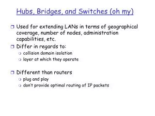
Hubs, Bridges, and Switches. Used for extending LANs in terms of geographical coverage, number of nodes, administration capabilities, etc. Differ in regards to: collision domain isolation layer at which they operate Different than routers plug and play

Hubs, Bridges, and Switches
E N D
Presentation Transcript
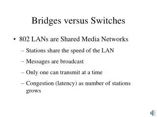
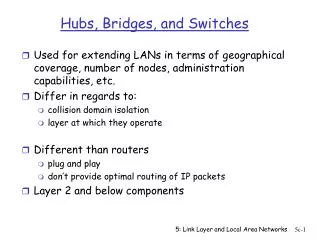
Hubs, Bridges, and Switches • Used for extending LANs in terms of geographical coverage, number of nodes, administration capabilities, etc. • Differ in regards to: • collision domain isolation • layer at which they operate • Different than routers • plug and play • don’t provide optimal routing of IP packets • Layer 2 and below components 5: Link Layer and Local Area Networks
Hubs • Physical Layer devices: essentially repeaters operating at bit levels: repeat received bits on one interface to all other interfaces • Hubs can be arranged in a hierarchy (or multi-tier design), with a backbone hub at its top 5: Link Layer and Local Area Networks
Hubs (more) • Each connected LAN is referred to as a LAN segment • Hubs do not isolate collision domains: a node may collide with any node residing at any segment in the LAN • Hub Advantages: • Simple, inexpensive device • Multi-tier provides graceful degradation: portions of the LAN continue to operate if one of the hubs malfunction • Extends maximum distance between node pairs (100m per Hub) 5: Link Layer and Local Area Networks
Hubs (more) • Hub Limitations: • Single collision domain results in no increase in max throughput; the multi-tier throughput same as the the single segment throughput • Individual LAN restrictions pose limits on the number of nodes in the same collision domain (thus, per Hub); and on the total allowed geographical coverage • Cannot connect different Ethernet types (e.g., 10BaseT and 100baseT) 5: Link Layer and Local Area Networks
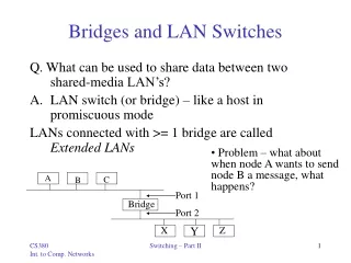
Bridges • Link Layer devices: they operate on Ethernet frames (i.e. layer 2 devices), examining the frame header and selectively forwarding a frame base on its destination • Bridge isolates collision domains since it buffers frames • When a frame is to be forwarded on a segment, the bridge uses CSMA/CD to access the segment and transmit 5: Link Layer and Local Area Networks
Bridges (more) • Bridge advantages: • Isolates collision domains resulting in higher total max throughput, and does not limit the number of nodes nor geographical coverage • Can connect different types of Ethernet since it is a store and forward device • Transparent: no need for any change to hosts LAN adapters 5: Link Layer and Local Area Networks
Backbone Bridge 5: Link Layer and Local Area Networks
Interconnection Without Backbone • Not recommended for two reasons: - Single point of failure at Computer Science hub - All traffic between EE and SE must path over CS segment 5: Link Layer and Local Area Networks
Bridge Filtering • Bridges learn which hosts can be reached through which interfaces and maintain filtering tables • A filtering table entry: (Node LAN Address, Bridge Interface, Time Stamp) • Filtering procedure: ifdestination is on LAN on which frame was received then drop the frame else{ lookup filtering table if entry found for destination then forward the frame on interface indicated; else flood; /* forward on all but the interface on which the frame arrived*/ } 5: Link Layer and Local Area Networks
Bridge Learning • When a frame is received, the bridge “learns” from the source address and updates its filtering table (Node LAN Address, Bridge Interface, Time Stamp) • Stale entries in the Filtering Table are dropped (TTL can be 60 minutes) 5: Link Layer and Local Area Networks
Disabled Bridges Spanning Tree • For increased reliability, it is desirable to have redundant, alternate paths from a source to a destination • With multiple simultaneous paths however, cycles result on which bridges may multiply and forward a frame forever • Solution is organizing the set of bridges in a spanning tree by disabling a subset of the interfaces in the bridges: Bridges talk to each other! 5: Link Layer and Local Area Networks
Bridges versus Routers • Both are store-and-forward devices, but Routers are Network Layer devices (examine network layer headers) and Bridges are Link Layer devices • Routers maintain routing tables and implement routing algorithms; bridges maintain filtering tables and implement filtering, learning and spanning tree algorithms 5: Link Layer and Local Area Networks
Routers versus Bridges • Bridges + and – + Bridge operation is simpler requiring less processing bandwidth (plug and play) - Topologies are restricted with bridges: a spanning tree must be built to avoid cycles - Bridges do not offer protection from broadcast storms (endless broadcasting by a host will be forwarded by a bridge) 5: Link Layer and Local Area Networks
Routers versus Bridges • Routers + and - + Arbitrary topologies can be supported, cycling is limited by TTL counters (and good routing prots) + Provide firewall protection against broadcast storms - Require IP address configuration (not plug and play) - Require higher processing bandwidth • Bridges do well in small (few hundred hosts) while routers are required in large networks (thousands of hosts) 5: Link Layer and Local Area Networks
Ethernet Switches • A new device came in 1990s • A switch is a device that incorporates bridge functions as well as point-to-point “dedicated connections” • A host attached to a switch via a dedicated point-to-point connection; will always sense the medium as idle; no collisions ever! • Ethernet Switches provide a combinations of shared/dedicated, 10/100/1000 Mbps connections 5: Link Layer and Local Area Networks
Ethernet Switches (more) • Some Ethernet switches support cut-through switching: frame forwarded immediately to destination without awaiting for assembly of the entire frame in the switch buffer; slight reduction in latency (rather than store-and-forward packet switching) • The cut-through switching will differ from store-and-forward switching only when the output buffer is empty • When output buffer is empty, there is no need to get the whole packet before sending it out in cut-through switching • Ethernet switches vary in size, with the largest ones incorporating a high bandwidth interconnection network 5: Link Layer and Local Area Networks
Ethernet Switches (more) Dedicated Shared 5: Link Layer and Local Area Networks
IEEE 802.11 Wireless LAN • Wireless LANs are becoming popular for mobile Internet access • Applications: nomadic Internet access, portable computing, ad hoc networking (multihopping) • IEEE 802.11 standards defines MAC protocol; unlicensed frequency spectrum bands: 900Mhz, 2.4Ghz • Basic Service Sets + Access Points Distribution System • Like a bridged LAN (flat MAC address) 5: Link Layer and Local Area Networks
Ad Hoc Networks • IEEE 802.11 stations can dynamically form a group without AP • Ad Hoc Network: no pre-existing infrastructure • Applications: “laptop” meeting in conference room, car, airport; interconnection of “personal” devices (see bluetooth.com); battelfield; pervasive computing (smart spaces) • IETF MANET (Mobile Ad hoc Networks) working group 5: Link Layer and Local Area Networks
IEEE 802.11 MAC Protocol CSMA Protocol: - sense channel idle for DISF sec (Distributed Inter Frame Space) -transmit frame (no Collision Detection) - receiver returns ACK after SIFS (Short Inter Frame Space) -if channel sensed busy then binary backoff NAV: Network Allocation Vector (min time of deferral) 5: Link Layer and Local Area Networks
Hidden Terminal Effect • CSMA inefficient in presence of hidden terminals • Hidden terminals: A and B cannot hear each other because of obstacles or signal attenuation; so, their packets collide at B • Solution? CSMA/CA • CA = Collision Avoidance 5: Link Layer and Local Area Networks
Collision Avoidance: RTS-CTS exchange • CTS “freezes” stations within range of receiver (but possibly hidden from transmitter); this prevents collisions by hidden station during data • RTS and CTS are very short: collisions during data phase are thus very unlikely (the end result is similar to Collision Detection) • Note: IEEE 802.11 allows CSMA, CSMA/CA and “polling” from AP CTS: clear to send RTS: request to send 5: Link Layer and Local Area Networks
Point to Point Protocol (PPP) • Point to point, wired data link easier to manage than broadcast link: no Media Access Control • Several Data Link Protocols: PPP, HDLC, SDLC, Alternating Bit protocol, etc • PPP (Point to Point Protocol) is very popular: used in dial up connection between residential Host and ISP; on SONET/SDH connections, etc • PPP is extremely simple (the simplest in the Data Link protocol family) and very streamlined 5: Link Layer and Local Area Networks
PPP Requirements • Packet framing: encapsulation of IP packets • bit transparency: must carry any bit pattern in the data field of the network protocol • error detection (no correction) • multiple network layer protocols • connection liveness (detection of link failure) • Network Layer Address negotiation: Hosts/nodes across the link must learn/configure each other’s network address (e.g. IP address) 5: Link Layer and Local Area Networks
Not Provided by PPP • error correction/recovery • flow control • sequencing • multipoint links (e.g., polling) 5: Link Layer and Local Area Networks
PPP Data Frame • Flag: delimiter (framing) • Address: does nothing (only one option) • Control: does nothing; in the future possible multiple control fields • Protocol: upper layer to which frame must be delivered (e.g., PPP-LCP, IP, IPCP, etc) 5: Link Layer and Local Area Networks
Byte Stuffing • For “data transparency”, the data field must be allowed to include the pattern <01111110> ; ie, this must not be interpreted as a flag • to alert the receiver, the transmitter “stuffs” an extra < 01111110> byte after each < 01111110> data byte • the receiver discards each 01111110 followed by another 01111110, and continues data reception 5: Link Layer and Local Area Networks
PPP Data Control Protocol • PPP-LCP establishes/releases the PPP connection; negotiates options • Starts in DEAD state • Options: max frame length; authentication protocol • Once PPP link established, IPCP (Control Protocol) moves in (on top of PPP) to configure IP network addresses etc. 5: Link Layer and Local Area Networks