Download
1 / 35
380 likes | 551 Vues
Fundamentals of telecommunications. Training materials for wireless trainers. Goals. To present the basics concepts of telecommunication systems with focus on digital and wireless. Basic Concepts. Signal Analog, Digital, Random Sampling Bandwidth Spectrum Noise Interference

E N D
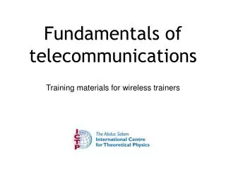
Fundamentals of telecommunications Training materials for wireless trainers
Goals To present the basics concepts of telecommunication systems with focus on digital and wireless
Basic Concepts • Signal • Analog, Digital, Random • Sampling • Bandwidth • Spectrum • Noise • Interference • Channel Capacity • BER • Modulation • Multiplexing • Duplexing
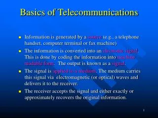
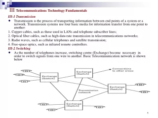
Telecommunication Signals • Telecommunication signals are variation over time of voltages, currents or light levels that carry information. • For analog signals, these variations are directly proportional to some physical variable like sound, light, temperature, wind speed, etc. • The information can also be transmitted by digital signals, that will have only two values, a digital one and a digital zero.
Telecommunication Signals • Any analog signal can be converted into a digital signal by appropriately sampling it. • The sampling frequency must be at least twice the maximum frequency present in the signal in order to carry all the information contained in it. • Random signal are the ones that are unpredictable and can be described only by statistical means. • Noise is a typical random signal, described by its mean power and frequency distribution. 5
Examples of Signals Random Signal AM modulated Signal FM modulated Signal
Sinusoidal Signal A ⊖ v(t)= A cos(wt - ⊖) 0 time -A A = Amplitude, volts w = 2*πf, angular frequency in radians f = frequency in Hz T = period in seconds, T= 1/f ⊖= Phase in degrees or radians
Spectral analysis and filters f3 f2 f1 Oscilloscope Spectrum Analyzer
Sampling t Analog Signal Sampling Circuit Sampled Signal The sampled signal can be quantized and coded to convert it to a digital signal. This is normally done with an ADC (Analog to Digital Converter). The recovery of the original signal is by means of a DAC.
Why Digital? • Noise does not accumulate when you have a chain of devices like it happens in an analog system: CD Versus Vinyl, VHS Vs DVD. • The same goes for the storing of the information. • Detection of a digital signal is easier than an analog signal, so they can have greater range. • Digital signals can use less bandwidth, as exemplified by the “digital dividend” currently being harnessed in many countries. • Digital circuits are easier to design and can achieve greater integration levels than analog circuits. • Digital signals can be encoded in ways that allow the recover from transmission errors, albeit at the expense of throughput.
Attenuation Received Signal Transmitted Signal
Interference • Any signal different from the one that our system is designed to receive that is captured by the receiver impairs the communication and is called interference. • Intra-channel interference originates in the same channel as our signal. • Co-channel interference is due to the imperfection of the filters that will let in signals from adjacent channels. 20
Information Measurement • I = log2 (1/Pe) • The information carried by a signal is expressed in bits and is proportional to the logarithm of the inverse of the probability of the occurrence of the corresponding event. • The more unlikely an event to happen, the more information its happening will carry. • Transmitting a message of an event that the receiver already knows carries no information. • The amount of information transmitted in one second is the capacity of the channel, expressed in bit/s. 21
Redundancy • Sending twice the same information is a waste of the system capacity that reduces the throughput. • Nevertheless, if an error occurs, the redundancy can be used to overcome the error. • Every error correcting code must use some sort of redundancy. 22
MoDem Transmission Medium 1 0 1 0 1 0 1 0 -Dem Mod Digital Signal Digital Signal Analog Signal
Comparison of modulation techniques 1 0 1 0 Digital Sequence ASK modulation FSK modulation PSK modulation QAM modulation, changes both amplitude and phase
BER Versus Eb/No From Wikipedia: http://en.wikipedia.org/wiki/Bit_error_rate
Comparison of modulation types BER of 10-6
Multiplexing A A A B C D B Multiplexer Demultiplexer B Communication Channel C C D D
Example: U.S. Television Channels Allocation Signal Power Channel 2 Channel 3 Channel 4 Channel 5 Channel 6 54 60 66 72 76 82 frequency, MHz 31
CDMA analogy Two messages superposed, one in yellow and one in blue A blue filter reveals what is written in yellow A yellow filter reveals what is written in blue
Types of transmissions • Simplex: • one way only, example, TV Broadcasting • Half-duplex: • the corresponding stations have to take turns to access the medium, example walkie-talkie. Requires hand-shaking to coordinate access. This technique is called TDD (Time Division Duplexing) • Full-duplex: • the two corresponding stations can transmit simultaneously, employing different frequencies. This technique is called FDD (Frequency Division Duplexing). A guard band must be allowed between the two frequencies in use. 33
Conclusions • The communication system must overcome the noise and interference to deliver the signal to the receiver. • The capacity of the communication channel is proportional to the bandwidth and to the logarithm of the S/N ratio. • Modulation is used to adapt the signal to the channel and to allow several signals to share the same channel. • Higher order modulation schemes allows for a higher transmission rate, but require higher S/N ratio. • The channel can be shared by several uses that occupy different frequencies, different time slots or different codes 34
Thank you for your attention For more details about the topics presented in this lecture, please see the book Wireless Networking in the Developing World, available as a free download in many languages: http://wndw.net/