Download
1 / 39
390 likes | 403 Vues
This project aims to build and operate a scaled-down prototype of the final focus system for a linear electron machine. The goal is to achieve a beam vertical size of 35 nm and a beam control position of 2 nm, with intra-train feedback. The project involves installation of magnets, beam size measurement using a laser interferometer, mechanical stabilization of the final doublet, and vibration measurements.

E N D
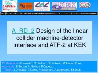
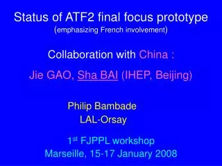
A_RD_2The ATF2 project @ KEKFinal Focus prototype of the linear electron machine May 16th 2008 Marc Verderi (LLR) for KEK, Saga Uni., Tohoku Univ., LAL, LAPP & LLR colleagues
ATF2 Goal • Build and operate a scaled-down prototype of the linear electron machine final focus system. • Target : • 35 nm beam vertical size • 2 nm beam control position, with intra-train feedback (like in ILC) • All in a reproducible and stable manner
extraction ATF2 (in construction) Final extraction line Temporary extraction line
A (very) few Highlights from KEK Tauchi Toshiaki (resp.) , Urakawa Junji, Sugahara Ryuhei, Kuroda Shigeru, Okugi Toshiyuki, Tatsuya Kume, And Sugiyama Akira (Saga univ.), Sanuki Tomoyuki (Tohoku univ.).
Pictures of Quadrupole installation From R. Sugahara talk The last magnet is going to the destination 10 - 20 Dec. 2007 : 19 concrete base blocks were installed 7 - 9 Jan. 2008 : 22 movers and 19 quad-systems were installed Installation is finished
Signal photons created by Compton effect on interference fringes Energy peaks at 30 MeV They have to be disentangled from bgk brem. photons Both signal and bgk photons come as a burst Exploit shower profile to disentangle signal from bgk Shintake monitorLaser interferometer for beam size measurementFrom Masahiro Oroku talk Signal Background
Observation of the Compton photon signalin Shintake g detector, using a “laser wire” CsI(Tl) crystals (from Belle group) wrapped with teflon sheet and the Al foil Laser on Data Laser off Geant4 340mm(18.4 X0) Background subtracted
LAPP contributionMechanical stabilization of Final Doublet A. Jeremie (resp.), N. Geffroy, B. Bolzon, G. Gaillard*, J.P. Baud* (*) No travel expenses expected
QD0FF QF1FF SF1FF SD0FF IP Sweeping 450.1 450.1 Shintake 200 Honda 200 76.2 180 76.2 180 100 100 100 100 SBPM SBPM SBPM SBPM FFTB 2.13 S3.00 FFTB 2.13 S3.00 QC3 QC3 380 785 380 785 2630 Final Doublet Elements to be supported& beam instrumentation devices • FD layout: • 2 quadrupoles • 2 sextupoles • 4 SBPMs • Beam pipe 400kg 30kg New responsability Cu:15kg
Relative stabilization ATF2 approach • Final Doublet (FD) elements and beam instrumentation devices (e.g. Shintake) need to have “fixed” related positions • Tolerance in relative motions < 6 nm (in a first stage) • To meet the 35 nm vertical size requirement • They are however too far apart, and too heavy together, to be put on a single stabilization device • Strategy adopted is to have both “floating” coherently with / on top of floor vibrations • Coherence length of floor motions (4-5 meters) large enough to allow this
Reuse of CLIC table for FD support • CLIC table at CERN reused: • But in passive mode • And adjusted at LAPP to beam line height • Have to care that the table transmits “fully” all floor vibration frequencies • In the [0.1, 100] Hz range • In particular, this means • No attenuation of some frequencies • No presence of eigenfrequencies of the {table+ FD elements} system in this range • Basically equivalent to a large concrete block • But allows to stay flexible in support design • In particular, can be moved more easily
Adjust support to beam height • New spool feet under magnet mover Integrated RMS relative motion predicted at ATF2 between one sextuple and the honeycomb table Mover Relative motion between sextupole and table: 1.6nm only at 7Hz!
Table to floor attachment study :four feet vs. entire side attachment Start with a simulation of a simple block with “4-feet” or “entire side” boundary conditions, with or without mass on table No Mass 1400 kg Attachment to floor = 4-feet feigen = 26.2 Hz feigen = 56.2 Hz Lower eigenfrequency, but still suitable Attachment to floor = entire side feigen = 526.1 Hz feigen = 135.2 Hz
4 rigid feet attachement experimental setup Four adjustable rigid feet adjustable to avoid rocking of the table Beeswax for good vibration transmissions between floor and table Masses of 1188kg: weight of the magnets to put on the table Masses of 594kg
Magnitude of table transfer function Table on 4 feet First resonance of the table moving to lower frequencies with increasing weight on the table
Entire side attachment to floor experimental setup Good vibration transmissions between floor and table Bolt Beeswax No Mass No beeswax • Beeswax: • Excellent vibration transmission. • Easy to remove if needed. sling table beeswax Masses of 1188kg (equivalent to magnets weight) 3 plates
Magnitude of table transfer function Table on entire side Note in addition this is about half of the “4-feet” case No masses: no resonances below 100Hz Masses of 1188kg: first resonance at 92Hz
LAPP schedule for 2008 • April-May: new mover parts ready • May: ATF2 magnets arrive at LAPP • Arrived on Tuesday, this week ! • May-June: Vibration measurements with magnets, support and water flow • July: vibration measurements with BPM support • July: pack crates • September-October: shipment and installation
LAL contributionBeam orbit control and correction algorithms Ph. Bambade (resp.), J. Brossard, C. Rimbault, M. Alabau Pons, Y. Rénier, Guy Le Meur*, Francois Touze* (*) No travel expenses expected
“Flight Simulator” • Design and implement a simulation portable tool that provides a realistic emulation of the ATF2 machine hardware controls • Can be run both • in simulation mode • or in an actual machine control mode • Not limited to a unique “beam transport simulation engine” underneath • Interfaces Lucretia, MAD, SAD & PLACET beam codes • Common data structures in AML • Last but not least : provides safe, controlled access to ATF2 hardware controls • Effort to make a collaborative development of the software • at present, ATF2 control software is the responsibility of a private company • Workshop on AIL funding will take place at Orsay 18-20th of June ! • Operating currently the “flight simulator” in the actual control machine mode for the first time : • Read machine BPMs information • Compute feed-back corrections to be applied to the beam • And send correction to the beam line • Very first real results obtained !
Study explores in what extent can be varied the b* Originally motivated to start ATF2 with larger b* values More comfortable situation, less sensitive to non-linearities Study shows that beam size down to ~17 nm might be achievable ! Of large interest for CLIC machine, as demonstrating its chromaticity regime is feasible Such low b* values are also of interest for ILC “pushed” machine Is 37 nm vertical size the limit at ATF2 ?
Emittance in extraction line is known to be ~3 times worst than in damping ring Need to be understood, as may involve part of the extraction line that will remain for ATF2 phase LAL people have been asked to investigate the problem and coordinate the effort Together with extraction line instrumentation, activity promoted as an “R & D” task for ATF2 Extraction line commissioning
Investigations so far • Could magnets shared with damping ring be the cause of the effect ? • Explains only part of the problem…
LLR contributionEstimate of background from beam halo & beam dump with Geant4 Hayg Guler (post doc ANR) Marc Verderi (resp.)
Background estimation at ATF2 using Geant4 • Activity started at LLR in April 2007 • Postdoc ANR Hayg Guler • Use Geant4 to simulate the beam line + beam dump to estimate EM and neutron background levels • Neutron being mainly produced in the beam dump • Need in addition to perform a set of dedicated measurements to cross-check the simulation estimates • Defining currently a set a “light” devices to measure EM and neutron backgrounds • Designing it so that it could be gradually put in place, and adapted according to what we will learn
Motivations for background measurements • It is a “service task” to the ATF2 collaboration • Complementary to background measurements in beam monitors • It can be a way to “prototype” bkgd estimation for ILC: • Use the same beam transport tool (BDSIM, Royal Holloway) than ILC • Optic transport for beam central part, Geant4 for halo • Could we learn/invent a way to extrapolate from 105 electrons simulated in a beam to a typical 1010 electrons in real life ? • Other sizable sources of EM bkgd than beam halo @ ATF2 ? • Eg : beam gas ? • Is neutron production, in beam dump, well simulated in Geant4 ? • As electro- photo-nuclear cross-sections large at low energy (< 100 MeV typically), ATF2 can provide a valuable answer to ILC • Is neutron transport well simulated also ? • Eg does Geant4 simulate well neutron thermalization ? • …
Early measurements / observations made by Hayg in December 2007 • Use single CsI (pure) crystal + PM, ~1 meter from dump (in temporary extraction line), reading signal at oscilloscope • Observe a prompt peak (back-scattered photons) + delayed contribution due to neutrons thermalized in dump • Only “qualitative” agreement with (quick) simulation for now ! Dump (iron) CsI + PM Beam
Conclusion • KEK hospitality practice welcomes non-KEK people to bring “on the same foot” contributions to the ATF2 project • Making an accelerator based project driven as an HEP experiment • ATF2 offers a wide range of opportunities to invent and deploy techniques in “real life” conditions • Stabilization, beam control, background simulation… • Shintake interferometer, laser wire, etc… • And it is a human size experiment • AIL framework provides an actual help to better benefit of KEK hospitality • And helps in having exchanges and benefits between Japanese and French people • This is particularly true and useful for young physicists • Certainly contributed to a favorable context for decision of next long term stays in KEK (Ph. Bambade, Y. Renier, F. Gournaris, B. Bolzon)
QD0FF QF1FF SF1FF SD0FF IP Sweeping 450.1 450.1 Shintake 200 Honda 200 76.2 180 76.2 180 100 100 100 100 SBPM SBPM SBPM SBPM FFTB 2.13 S3.00 FFTB 2.13 S3.00 QC3 QC3 380 785 380 785 2630 New responsibility: BPM support • S-band Cavity-BPM team: • BPM design and fabrication: KNU • BPM support design and fabrication : LAPP and SLAC • BPM electronics: KEK and UK Cu:15kg
Need to fit with IP instrumentation Up View Lateral View FD support