Download
1 / 18
180 likes | 290 Vues
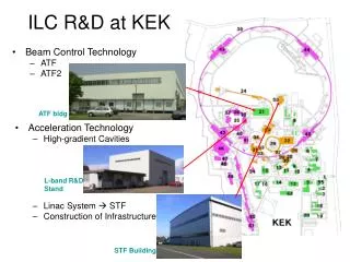
ATF2 ILC Final Focus Test Beam Line at KEK-ATF. References : ATF2 Proposal, KEK Report 2005-2 ATF2 Proposal Vol.2, KEK Report 2005-9 ホームページ: http://atf.kek.jp/collab/ap/projects/ATF2/index.php. 110 authors (25 reseach institutes) in the proposal. ATF2 Final Goal.

E N D
ATF2 ILC Final Focus Test Beam Line at KEK-ATF References : ATF2 Proposal, KEK Report 2005-2 ATF2 Proposal Vol.2, KEK Report 2005-9 ホームページ:http://atf.kek.jp/collab/ap/projects/ATF2/index.php
ATF2 Final Goal Ensure collisions between nanometer beams; i.e. luminosity for ILC experiment Optics and bean tuning Stabilization Reduction of Risk at ILC
Mode-I A. Achievement of 37nm beam size A1) Demonstration of a new compact final focus system; proposed by P.Raimondi and A.Seryi in 2000, A2) Maintenance of the small beam size (several hours at the FFTB/SLAC) Mode-II B. Control of the beam position B1) Demonstration of beam orbit stabilization with nano-meter precision at IP. (The beam jitter at FFTB/SLAC was about 20nm.) B2) Establishment of beam jitter controlling technique at nano-meter level with ILC-like beam (2008 -?)
Optics v3.5, 1 July 2006 final focus diagnostic reduction of dispersion 6m テキスト west
ATF2 beam line and ATF extraction line ATF2 beam line and ATF extraction line ATF2 beam line ATF extraction line
Magnets and Instrumentation at ATF2 22 Quadrupoles(Q), 5 Sextupoles(S), 3 Bends(B) in downstream of QM16 All Q- and S-magnets have cavity-type beam position monitors (QBPM). 3 Screen Monitors 5 Wire Scanners or Laserwires 5 Strip-line BPMs 5 Steering (V,H) Magnets 53 m QM16 V H V H V H 3.5m BSM QF1 QD0 B2 SD4 SF5 B5 SF6 B1 SF1 SD0 CLIC table IP Shintake Monitor ( beam size monitor, BSM with laser interferometer ) QBPMs (100nm ) and IPBPM ( 2nm ) at IP MONALISA ( nanometer alignment monitor with laser interferometer ) Laserwire ( beam size monitor with laser beam ) IP intra-train feedback system with latency of less than 150ns Magnet movers for Beam Based Alignment (BBA) High Available Power Supply (HA-PS) system for magnets
Optics at ATF2 electron beam SF5 SF6 SD4 SF1 SD0 F B1 B2 B5 IP D
QBPM in a Q-magnet Q-magnet (KEK, PAL, SLAC) (IHEP, SLAC KEK) Mover (SLAC) Concrete Support (KEK)
HA-PS system ( SLAC ) • Example : a power system with Ethernet control that will provide 200A in a 4 out 5 redundant module configuration. Test result with 3+1 system (150A) switch off 1 module B=3.1kG ΔB=-100G for a bend 200ms Voltage short time : 2-3ppm long time : 5ppm temperature : 2.5ppm/℃
CERN Stacis 2000 (CLIC) table currently in Annecy, France. (LAPP, CERN) Length:240 Width:90 Bloc:61 Total:87.5 Foot:26.5 Values are in cm and measured directly on the table with a tape-measure. Static load capacity per foot (there a 4) 182 kg to 1590 kg. Honeycomb bloc has a weight of 731kg.
(KEK, KNU) IP-BPM Rectangular cavity for X-Y isolation (-50dB) •2 Cavities in 1 block •2 Y ports and 2 X ports in 1 Cavity Goal : 2nm position resolution Sensor Cavity X Port (61.45 x 48.58 x 6mm3) 11 cm 14 cm Y Port 14 cm Wave guide Beam Pipe Slot (6 x 12 mm2) Preliminary beam test result : Position resolution for 1 hour run 8.72 +- 0.28 (stat.) +- 0.35 (sys.) nm ( ICT = 0.68 x 10¹⁰ e-/bunch, dynamic range = 4.96 um ) 1h Residual vs Time Residual of (Y2I – Y2Ipredicted)
(Univ. of Tokyo, KEK) Interference fringes as a reference Scanning electron beam Electron beam to be measured Schematics of Shintake MonitorMeasure beam size using phase (=position and period) of interference fringe as a reference γ-ray modulated by interference fringes
IP intra-train feedback system (Oxford) • Last line of defence against relative beam misalignment • Measure vertical position of outgoing beam and hence beam-beam kick angle • Use fast amplifier and kicker to correct vertical position of beam incoming to IR FONT – Feedback On Nanosecond Timescales
( RHUL, Oxford) Laserwire
distance meter Retro-reflector Interference pattern sensitive to perpendicular motion of retro-reflector (Oxford) MONALISA Monitoring of Alignment and Stabilization with high Accuracy to monitor the relative displacement between QD0 and Shintake monitor at Nanometer • Need 2 tools, both with nm type resolutions over a few m. • Straightness Monitormeasuring motion perpendicular to line of sight. Main tool to measure the relative motion of objects • Distance meter: • Frequency scanning interferometer • Can also provide perpendicular measurements if several measurements are combined to do triangulation. • Combine both measurements into one system! MONALISA
Cost Breakup, 26 Jan.07 Total 5.7 Oku-yen CF:floor, shield etc. magnets power supplies magnet supports including movers CF :Infrastructure alignment commissioning tools vacuum Shintake monitor Monalisa control Q-BPMs laserwire feedback
ATF2 Schedule Present ATF2 ON 1. International Construction and Operation; Mini-ILC 2. Forefront of Accelerator Technological R&D 3. Human Resource Development for ILC 4. Commissioning in October 2008