Electric Power Grid
45. 40. Load angle in degrees. 35. CONV-CONV. CONV-PSS_CONV. 30. DHP-CONV. DHP-DHP. 25. 10. 11. 12. 13. 14. 15. 16. 17. 18. 19. 20. Time in seconds – Alternator #2. 50. CONV-CONV. 45. CONV-PSS-CONV. DHP-CONV/DHP. 40. Load angle in degrees. 35. 30. 25. 20. 15. 10.

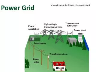
Electric Power Grid
E N D
Presentation Transcript
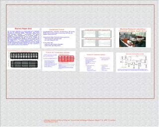
45 40 Load angle in degrees 35 CONV-CONV CONV-PSS_CONV 30 DHP-CONV DHP-DHP 25 10 11 12 13 14 15 16 17 18 19 20 Time in seconds – Alternator #2 50 CONV-CONV 45 CONV-PSS-CONV DHP-CONV/DHP 40 Load angle in degrees 35 30 25 20 15 10 15 20 25 Time in seconds – Alternator #1 On-line training result of MLP trained with BP Machines Research Laboratory University of Natal, South Africa Off-line testing result of MLP trained with BP FACTS G8 26 28 29 G10 8 27 10 9 25 G9 31 24 18 Load Angle Response for an Inductive Load Addition at bus 7 for P = 0.3 pu & Q = 0 pu FACTS 39 32 G6 17 16 6 15 G1 21 14 33 1 12 22 34 19 35 11 13 36 37 23 30 4 2 20 G4 G2 7 5 3 G7 38 G3 G5 • A turbogenerator - nonlinear, non-stationary, fast acting, MIMO device, wide range of operating conditions and dynamic characteristics. • Conventional AVRs, PSSs and turbine governors • linearized power system model • one operating point (OP). • At any other Ops • generator performance degrades • undesirable operating states. Electric Power Grid The increasing complexity of a modern power grid highlights the need for advanced system identification and control techniques for the power system. This poster displays work using intelligent nonlinear identification and control techniques. Each turbogenerator in the power system is equipped with a neuroidentifier, which is able to identify its particular turbogenerator and the rest of the network to which it is connected from moment to moment, based on only local measurements. Each neuroidentifier can then be used in the design of a nonlinear neurocontroller for each turbogenerator in such a multimachine power system. Results for the neuroidentifiers are presented to prove the validity of the concept. The FACTS devices and their benefits in power system control are also presented. Conventional Control NEW ENGLAND POWER SYSTEM Flexible AC Transmission Systems Applications of FACTS devices: Main types of FACTS devices are: Steady State applications • • Static Var Compensators (SVC’s) Dynamic Applications • Thyristor Controlled Series • Compensators (TCSC’s) • Static Synchronous Compensator (STATCOM) • Unified Power Flow Controller (UPFC) • Dynamic Applications • Steady State Applications: - Transient Stability - Voltage limits - Dampening - Thermal limits • - Loop flows - Post Contingency Voltage Location of FACTS devices can be determined using Heuristic techniques such as Genetic Algorithm, Adaptive Critic Designs and Power Flow Performance Index, etc. - Control - Short circuit levels - Voltage Stability - Subsynchronous resonance. Homeland Security and Force Protection – Science and Technology Conference, August 7 -8 , 2002, Ft Leonard Wood, Missouri, USA