Download
1 / 24
240 likes | 361 Vues
Hybrid Simulation for the Assessment of Semi-Rigid Partial-Strength Steel Frames in Seismic Regions. Quake Summit 2012 July 11, 2012 Boston, Massachusetts Hussam N. Mahmoud, Ph.D. Colorado State University. Overview. Introduction Structure Design Hybrid Simulation Approach

E N D
Hybrid Simulation for the Assessment of Semi-Rigid Partial-Strength Steel Frames in Seismic Regions Quake Summit 2012 July 11, 2012 Boston, Massachusetts Hussam N. Mahmoud, Ph.D. Colorado State University
Overview • Introduction • Structure Design • Hybrid Simulation Approach • Experimental module • Analytical module • Experimental Results and Observations • Conclusion • Questions
Damage to Welded Connections • Numerous examples of brittle fracture of welded moment connections, Northridge (1994), Kobe (1995) • Fracture initiation at the connection (backing bar detail) • Poor design practice • Poor toughness Introduction Structure Design Exp. Module Ana. Module Results Conclusions
Current Limitations Subassembly FEM Analysis Experimental Testing Realistic M-q Frame with rotational springs Idealized M-q Introduction Structure Design Exp. Module Ana. Module Results Conclusions
SMRF, Typ. 30 ft 30 ft 30 ft 30 ft 30 ft 30 ft 13.5 ft 15 ft Specimen Design • The structure is 2-story, 4-bay longitudinal and 2-bay transverse • The lateral load resisting system is SMRF designed using IBC 2006 • Load combination of 1.0 DL + 10 psf (partitions) + 0.25 LL + EQ W 14 x 159 W 18 x 40 Experimental Component Introduction Structure Design Exp. Module Ana. Module Results Conclusions
Specimen Design • Connection is designed as top-and seat-angles with double web-angles • According to EC 3 with capacity of 70%, 50%, and 30% of the beam plastic moment Introduction Structure Design Exp. Module Ana. Module Results Conclusions
Hybrid Simulation Approach Calc. forces Computational: FEA Target Disp. {u} Simulation Coordinator {F} Measured forces Experimental: LBCB Measure forces Introduction Structure Design Exp. Module Ana. Module Results Conclusions
Small-Scale Validation Small-Scale Setup Rubber Small-Scale Setup Steel Introduction Structure Design Exp. Module Ana. Module Results Conclusions
Small-Scale Validation Introduction Structure Design Exp. Module Ana. Module Results Conclusions
Control Development x2,y2,dq2 (x2+dx2, y2+dy2, dq2) Y (x3+dx3, y3+dy3, dq3) q LBCB1 X x3,y3,dq3 [T] LBCB2 (x1+dx1, y1+dy1, dq1) x1,y1,dq1 Fixed B.C. [T]-1 Y q X SIMCOR Space (3 control points) LBCBs Space (2 control points) Introduction Structure Design Exp. Module Ana. Module Results Conclusions
Control Development • Elastic deformation • Problem Definition • LBCB platform movement controlled internally • LBCB frame, reaction wall/floor have finite stiffness • Internal actuator displacements include both specimen and external deformations • Solution • An external measurement and feedback system was developed • 3 DOF (x,y, rz) for each LBCB for a total of 6 DOFs • System of 6 high tension string pots with low friction connections • Precisely monitors and accounts for the movement of the LBCB platform in space Introduction Structure Design Exp. Module Ana. Module Results Conclusions
Full-Scale Setup Introduction Structure Design Exp. Module Ana. Module Results Conclusions
Instrumentation Control Control Development Introduction Structure Design Exp. Module Ana. Module Results Conclusions
Instrumentation • Global • Still images and videos • Global drift • Global strain • M-q • Local • Still images and videos • Bolt slip • Localized strain • Angle deformation relative to the beam and column Introduction Structure Design Exp. Module Ana. Module Results Conclusions
Cyclic Loading of the Model Introduction Structure Design Exp. Module Ana. Module Results Conclusions
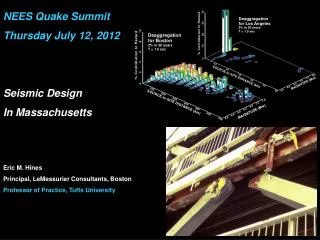
Record Selection • The Loma Prieta, PGA = 0.26 g • USGS 1662 Emeryville, 77 km from the epicenter • Soft soil (Vs = 199 m/s) Introduction Structure Design Exp. Module Ana. Module Results Conclusions
Hybrid Results Introduction Structure Design Exp. Module Ana. Module Results Conclusions
Hybrid Simulation Results (local) 43.6% Mpbeam 82% Mpbeam 65.2% Mpbeam • Hybrid 30% Mpbeam Introduction Structure Design Results Exp. Module Ana. Module Conclusions
Hybrid Simulation Results (global) Introduction Structure Design Results Exp. Module Ana. Module Conclusions
Hybrid Simulation Results (global) IDR limit of 5% IDR limit of 2.5% Introduction Structure Design Results Exp. Module Ana. Module Conclusions
Conclusions • A new Hybrid simulation approach for the seismic evaluation of semi-rigid steel frames is executed • Three simulations were conducted • Large hysteretic loops characterize the connection behavior • No failure in any of the connection components • The maximum moment sustained by the 70% Mpbeam, 50% Mpbeam, and 30% Mpbeam connections is 3,222 kips.in (82% Mpbeam), 2,556 kips.in (65% Mpbeam), and 1,708 kips.in (43% Mpbeam), respectively Introduction Structure Design Results Exp. Module Ana. Module Conclusions
Conclusions (cont.) • The corresponding rotations are 0.0196 rad, 0.0271rad, and 0.3400rad, respectively • The procedure used to scale the records does not allow for direct comparison with the interstory drift limits in ASCE 41-10 • The 50%Mpbeam and 70% Mpbeamframe are deemed acceptable for LS limit state (DBE) while the 30%Mpbeam violates the requirements as its roof drift ratio is calculated to be 2.70%, which is slightly higher than the limit of 2.5% for DBE • For the expected maximum period elongation, the demand is always higher than the DBE and in some cases even higher than the MCE Introduction Structure Design Results Exp. Module Ana. Module Conclusions
Mid-America Earthquake Center Acknowledgements • Dr. Elnashai, Dr. Spencer, and Dr. Kuchma • Fellow former graduate students at UIUC • NEES staff at UIUC (MUST-SIM) • The analytical and experimental investigations on the steel frames were supported by the MAE Center • The experimental investigation was supported by NEES (shared-use)