Download
1 / 35
350 likes | 520 Vues
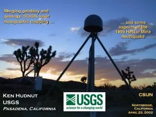
Merging geodesy and geology: SCIGN, laser topographic mapping …. … and some aspects of the 1999 Hector Mine earthquake. Ken Hudnut USGS Pasadena, California. CSUN Northridge, California April 23, 2002. The major objectives of the SCIGN array are:.

E N D
Merging geodesy and geology: SCIGN, laser topographic mapping … … and some aspects of the1999 Hector Mine earthquake Ken Hudnut USGS Pasadena, California CSUN Northridge, California April 23, 2002
The major objectives of theSCIGN array are: • To provide regional coverage for estimating earthquake potential throughout Southern California • To identify active blind thrust faults and test models of compressional tectonics in the Los Angeles region • To measure local variations in strain rate that might reveal the mechanical properties of earthquake faults • In the event of an earthquake, to measure permanent crustal deformation not detectable by seismographs, as well as the response of major faults to the regional change in strain
“SCIGN data quality is excellent – probably the best of any network in the world…”– Tom Herring, 6/19/01 Scientific Director, UNAVCO at the 2001 SCIGN Annual Meeting
Plate Boundary Observatory (PBO) • Existing sites: • PANGA, BARD, EBRY, BARGEN, LVC, SCIGN • New sites: • Backbone and clusters: • Alaska and Cascadia • Volcanic complexes • San Andreas fault zone
PBO San Andreas plan • Existing sites: • BARD, SCIGN, LVC, • and BARGEN • New sites: • Clusters along San Andreas fault, especially along transitions from creeping to locked sections
High resolution topography along surface rupture of the October 16, 1999 Hector Mine, California Earthquake (Mw7.1) from Airborne Laser Swath Mapping HUDNUT, K. W., U. S. Geological Survey BORSA, A., IGPP/SIO, UCSD GLENNIE, C., Aerotec LLC MINSTER, J.-B., IGPP/SIO, UCSD In press, Bulletin of the Seismological Society of America Special Issue on the Hector Mine earthquake (2002) http://pasadena.wr.usgs.gov/office/hudnut/BSSA_ALSM/
ALSM, InSAR and TM imagingand mapping before & after Laser scan of land surfaces and urban infrastructure – buildings & lifelines - damage assessment ALSM – 9/11/01 NYC LANDSAT 7 – earthquake damage - Bhuj, India Pre- and post-disaster images can be differenced to measure damage and track recovery
Active Faults in Southern California Hector Mine earthquake
Surface Rupture • Previously mapped, but un-named • Lavic Lake fault in recognition of breaks through dry lake bed • Up to 5.25 meters of right-lateral motion • 48 km overall length of surface rupture • Only ruptured once prior through ~50 ka alluvium
Hector Mine (Mw7.1) Photo by Paul ‘Kip’ Otis-Diehl, USMC, 29 Palms
ALSM (Scanning LIDAR imaging) • Slow, precise helicopter flight line data acquisition at 200-300 m AGL. • 6888 pps near infra-red (1064 nm) laser. • Scan Width: +/- 20 degrees. Nominally, 180 meters full-width. • 200 pulses across swath, ~ 80cm spacing. • Footprint Diameter: Nominally 40cm. • Half-meter posting, 15cm horizontal one-sigma absolute accuracy specified. • Integrated GPS & INS navigation and attitude determination. • Pitch Mirror Correction: maximum +3.5/-6.5 degrees (+ forward bias).
R v v r r R Geolocation Vectors and Error Sources Vector from CMearth to GPS phase center Magnitude & directional errors both are stochastic, time and location variant. Vector from GPS phase center to laser Magnitude error is constant if no airframe flexing. Directional error due to constant and time-varying biases in INS. Vector from laser to ground footprint Magnitude error due to timing, instrument and atmospheric delays. Directional error from constant mirror mounting offsets and time-varying biases in reporting of scan angles (both pitch and roll). Note: additional errors due to imperfect synchronization of GPS, INS, mirror scan and laser firing times must be modeled and removed as well.
Flight Plan • Two overlapping swaths • 200-500m mapped width • 70 km long • GPS network ≥ 1 Hz • Temporary GPS stations • Cross-swath spurs • Roll/Pitch/Yaw calibration maneuvers over dry lake • Flights over well-mapped Hector Mine
GPS Sites at ≥1Hz During ALSM Mission Calibration maneuvers at Hector Mine and Lavic Lake 1Hz 2Hz AGMT HCMN NBPS OPCL OPCX OPRD BMHL OPBL OPCP RDMT SIBE TROY
Southwest Corner of Lavic Lake dry lake bed for calibrations
New methods to explore, new synergies between data types (e.g., GPS & ALSM) 1999 Hector Mine earthquake surface rupture • Combinations of seismic, geologic, and geodetic data in new ways • Source modelling • Hazard modelling • Cross-overs between fields • Geology and geodesy with InSAR and ALSM • Seismology and geodesy with high-rate GPS
ALSM-Derived Contours of Bullion Mountain Segment (blue lines are 1-foot contours)
To assess geodetic capability of repeat-pass ALSM:calibration requirements • Geometry: mount angles, scan offsets, GPS-Laser vector, GPS antenna phase center. • Delays: electronic, optical, atmospheric. • Reference point on laser platform. • Timing of various components: e.g. INS vs. GPS vs. mirror attitude sensors. • Stabilization platforms (delays, accuracy). • Detectors (thresholds, amplitude-range “walk”).
Exploded ordnance (crater) Lavic Lake Roll & Pitch Maneuvers pitch maneuvers
10 cm vert. 15 cm vert.
Cal/Val Maneuver Stacks • Ramp probably due to roll or scan bias • End biases are real (low roll/ pitch section) • Excellent shot- to-shot varia-bility (5cm rms)
Geological quantification and questions • Tectonic interpretation of strain release in great earthquakes from their surface rupture • Basic documentation of surface rupture • e.g., Kurushin et al. (1997) study of 1957 Gobi-Altay eq. • How does slip vary along-strike? • e.g., need to assess variance and error in slip rate estimates from paleoseismic methods • e.g., Barka et al. (2002) and Rockwell et al. (2002) extensive studies of 1999 eq.’s in Turkey and similar studies of Hector Mine earthquake (in press, BSSA) • is high-frequency energy radiated from fault? • Does slip vary from one earthquake to the next? • can detailed topographic mapping of geomorphic features along the fault be modeled by repeats of exactly the same slip in successive earthquakes, or must slip vary in order to explain the topography? • slip variation models for earthquake recurrence strongly influence seismic hazard analyses – assumptions made in these analyses necessarily simplify faulting processes, with societal repurcussions
Conclusions - and some open questions • Airborne LIDAR imaging (ALSM) offers remarkable promise for geomorphology, even over inaccessible or vegetated areas • Commercial operations are reliable and affordable on well-specified targets with carefully designed deployments (same as photogrammetry) • CAL-VAL maneuvers are essential for geodetic-quality mapping of geomorphological features • Turning ALSM into a geodetic-quality tool requires careful calibration and considerable analysis • Slip estimation: • has been initially developed demonstrated • new and improved methods are being developed • systematic measurement along the surface rupture will be done and then compared with geologic estimates, InSAR and other methods • quantitative assessment of slip variation along-strike • dynamic faulting models – is high-frequency energy radiating from the fault? • Quantitative geomorphology • Model tectonic landform evolution • Did topographic features form as a result of exactly repeated slip distributions? • Can topography be explained by only certain combinations of slip in past events?