Download
1 / 50
500 likes | 519 Vues
Learn about image sensors, camera parameters, filters, noise, and reconstruction tools in computational photography. Dive into techniques for improving camera performance and exploring futuristic imaging technologies beyond traditional photography.

E N D
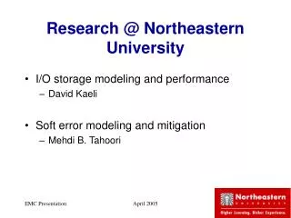
Northeastern University, Fall 2005CSG242: Computational Photography Ramesh Raskar Mitsubishi Electric Research Labs Northeastern University Dec 7, 2005 Course WebPage : http://www.merl.com/people/raskar/photo/course/
Plan for Today • Assignment 4 • Paper reading • Topics • Sensors • Computational Imaging beyond Photography • Mok Oh, Mok3d.com • Discussion on Project Proposals
Reading Paper Presentations 15 minutes: 10 minute presentation, 5 minutes for discussion Use Powerpoint slides, Bring your own laptop or put the slides on a USB drive, (print the slides to be safe) Format: Motivation Approach (New Contributions) Results Your own view of what is useful, what are the limitations Your ideas on improvements to the technique or new applications (atleast 2 new ideas) It is difficult to explain all the technical details in 15 minutes. So focus on the key concepts and give an intuition about what is new here. Ignore second order details in the paper, instead describe them in the context of the results. Keep the description of the approach simple, a rule of thumb: no more than 3 equations in your presentation. Most authors below have the powerpoint slides on their websites, so feel free to use those slides and modify them. Be careful, do not simply present all their slides in sequence. You should focus on only the key concepts and add your own views. If the slides are not available on the author website, copy paste images from the PDF to create your slides. Sometimes you can send email to the author, and s/he will send you the slides.
AIntroduction Digital photography compared to film photography Image formation, Image sensors and Optics BUnderstanding the Camera Parameters: Pixel Resolution, Exposure, Aperture, Focus, Color depth, Dynamic range Nonlinearities: Color response, Bayer pattern, White balance, Frequency response Noise: Electronic sources Time factor: Lag, Motion blur, Iris Flash settings and operation Filters: Polarization, Density In camera techniques: Auto gain and white balance, Auto focus techniques, Bracketing CImage Processing and Reconstruction Tools Convolution, Overview Gradient domain operations, Applications in fusion, tone mapping and matting Graph cuts, Applications in segmentation and mosaicing Bilateral and Trilateral filters, Applications in image enhancement DImproving Performance of Camera Dynamic range: Variable exposure imaging and tone mapping, Frame rate: High speed imaging using multiple cameras Pixel resolution: Super-resolution using jitter Focus: Synthetic Aperture from camera array for controlled depth of field EImage Processing and Reconstruction Techniques Brief overview of Computer Vision techniques: Photometric stereo, Depth from defocus, Defogging Scene understanding: Depth edges using multiple flashes, Reflectance using retinex Denoising using flash and no flash image pairs Multi-image fusion techniques: Fusing images taken by varying focus, exposure, view, wavelength, polarization or illumination Photomontage of time lapse images Matting Omnidirectional and panoramic imaging FComputational Imaging beyond Photography Optical tomography, Imaging beyond visible spectrum, Coded aperture imaging, multiplex imaging, Wavefront coded Microscopy Scientific imaging in astronomy, medicine and geophysics GFuture of Smart and Unconventional Cameras Overview of HDR cameras: Spatially adaptive prototypes, Log, Pixim, Smal Foveon X3 color imaging Programmable SIMD camera, Jenoptik, IVP Ranger Gradient sensing camera Demodulating cameras (Sony IDcam, Phoci) Future directions Today
Schedule • Dec 2nd (Friday) • Hw 4 due Midnite • Dec 7th • Computational Imaging Beyond Photography • Special lecture: Mok3 • Dec 15th (Exam week) • In class exam (instead of Hw 5) • Final Project Presentation
Assignment 4: Playing with Epsilon ViewsSee course webpage for details • Resynthesizing images from epsilon views (rebinning of rays) • http://groups.csail.mit.edu/graphics/pubs/siggraph2000_drlf.pdf In this assignment, you will use multiple pictures under slightly varying position to create a large synthetic aperture and multiple-center-of-projection (MCOP) images You will create (i) An image with programmable plane of focus (ii) A see-through effect --------------------------------------------------------- (A) Available set http://www.eecis.udel.edu/~yu/Teaching/toyLF.zip Use only 16 images along the horizontal translation (B) Your own data set Take atleast 12-16 pictures by translating a camera (push broom) The forground scene is a flat striped paper Background scene is a flat book cover or painting Choose objects with vibrant bright saturated colors Instead of translating the camera, you may find it easier to translate the scene Put the digital camera in remote capture time lapse interval mode (5 second interval) Effect 1: Programmable focus Rebin rays to focus on first plane Rebin rays to focus on back plane Rebin rays to focus on back plane but rejecting first plane Effect 2: MCOP images Rebin rays to create a single image with multiple views Useful links http://groups.csail.mit.edu/graphics/pubs/siggraph2000_drlf.pdf
Intensity Gradient in 1D Intensity Gradient 105 105 1 1 I(x) G(x) Gradient at x,G(x) = I(x+1)- I(x)Forward Difference
Reconstruction from Gradients Gradient Intensity 105 105 ? ? 1 1 G(x) I(x) For n intensity values, about n gradients
Reconstruction from Gradients Gradient Intensity 105 105 ? 1 1 G(x) I(x) 1D Integration I(x) = I(x-1) + G(x) Cumulative sum
Gradient Camera Sensing Pixel Intensity Difference with Locally Adaptive Gain Ramesh Raskar, MERL Work with Jack Tumblin, Northwestern U, Amit Agrawal, U of Maryland
Natural Scene Properties Intensity Gradient 105 105 1 1 x x Intensity Histogram Gradient Histogram 1 105 -105 105
Original Image Intensity values ranging from 0 to 1800Intensity ramp plus low contrast logo Intensity Camera Image 8 bit camera for 1:1000 rangeProblem: . saturation at high intensity regions Locally Adaptive Gain Pixel divided by the average of local neighborhood. Thus the low frequency contents are lost and only detail remains. Log Camera Image 8 bit log for 1:106range Problem: Visible quantizationeffects at high intensities Gradient Camera Image In proposed method, we sense intensity differences. We use a 8 bit A/D with resolution of log(1.02) to capture 2% contrast change between adjacent pixels. Notice that the details at both high and low intensities are captured.
Gradient Camera • Two main features • Sense difference between neighboring pixel intensity At each pixel, measure (x , y ) , x = Ix+1,y -Ix,y , y = Ix,y+1 -Ix,y • With locally adaptive gain • Gradient camera is very similar to locally adaptive gain camera • Locally Adaptive Gain Camera • Gain is differentfor each pixel • Problem: Loses low frequency detail and preserves only high frequency features (edges) • Gradient Camera • The gain is same for four adjacent pixels • Difference between two pixels is measured with same gain on both pixels • Reconstruct original image in software from pixel differences by solving a linear system (solving Poisson Equation)
Camera Pipeline On-board Hardware Software Difference between pixels Local gain adaptive to difference 2D Integration to reconstruct the image
Detail Preserving Intensity Camera Log Intensity Camera Gradient Camera Intensity cameras capture detail but lose range Log cameras capture range but lose detail
Quantization Intensity Histogram 1 105 Gradient Histogram Original Image Uniform quantization 3 bits -105 105 GradCam requires fewer bits In the reconstructed image, error is pushed to high gradient pixel positions which is visually imperceptible Log Uniform quantization 3 bits Log Uniform gradients quantization 3 bits
High Dynamic Range Images Scene Intensity camera saturation map Gradient camera saturation map Intensity camera fail to capture rangeGradients saturate at very few isolated pixels
3D Cameras • Time of flight or phase • ZCam • Canesta • Phase Decoding of modulated illumination • Phase difference = depth • Magnitude = reflectance • Structured Light • Binary coded light and triangulation
Novel Sensors • Gradient sensing • HDR Camera, Log sensing • Line-scan Camera • Demodulating • Motion Capture • 3D
Fantasy Configurations • ‘Cloth-cam’: ‘Wallpaper-cam’elements 4D light emission and 4D capture in the surface of a cloth… • Floating Cam: ad-hoc wireless networks form camera arrays in environment… • Other ray sets:Multilinear cameras, canonical ‘basis’ cameras(linear combination of 8 types) McMillan’04, ‘05
Future Directions • Smart Lighting • Light stages, Domes, Light waving, Towards 8D • Computational Imaging outside Photography • Tomography, Coded Aperture Imaging • Smart Optics • Handheld Light field camera, Programmable imaging/aperture • Smart Sensors • HDR Cameras, Gradient Sensing, Line-scan Cameras, Demodulators • Speculations
Computational Imaging Images Without Optics: X-rays, Gamma Rays don’t bend! • Computed Tomography • Coded Aperture Inverse Imaging: Computing Instead of Fancy Optics • Wavefront Coding ™
Computer Tomography • http://info.med.yale.edu/intmed/cardio/imaging/techniques/ct_imaging/
Computer Tomography • http://info.med.yale.edu/intmed/cardio/imaging/techniques/ct_imaging/
f(x,y) v F(u,v) u Computerized Tomography • X-rays pass thru 2D solid f() to form a 1-D “shadow’ image p2. • The Fourier Transform of p2() gives us 1D slice of • Of the Fourier Transform of the entire body f(). p1(x) p2(x)
The Fourier projection-slice theorem(a.k.a. the central section theorem) • P(t) is the integral of g(x,y) in the direction • G(u,v) is the 2D Fourier transform of g(x,y) • G(ω) is a 1D slice of this transform taken at • -1 { G(ω) } = P(t) ! P(t) G(ω) (from Kak)
Reconstruction of g(x,y)from its projections • add slices G(ω) into u,v at all angles and inverse transform to yield g(x,y), or • add 2D backprojections P(t, s) into x,y at all angles P(t) P(t, s) G(ω) (from Kak)
Computerized Tomography Original (simulated) 2D image 8 projections- Frequency Domain 120 projections- Frequency Domain Reconstruction from 120 projections Reconstruction from 8 projections
Reconstruction using Algebraic Reconstruction Technique (ART) • applicable when projection angles are limitedor non-uniformly distributed around the object • can be under- or over-constrained, depending on N and M N image cells, M projectionrays pi = projection alongray i fj = value ofimage cell j wij = contribution by cell j to ray i (a.k.a. resampling filter) (from Kak)
Borehole tomography • receivers measure end-to-end travel time • reconstruct to find velocities in intervening cells • must use limited-angle reconstruction method (like ART) (from Reynolds)
mapping ancient Rome using explosions in the subways and microphones along the streets? Applications mapping a seismosaurus in sandstone using microphones in 4 boreholes and explosions along radial lines
Coded-Aperture Imaging • Lens-free imaging! • Pinhole-camera sharpness,without massive light loss. • No ray bending (OK for X-ray, gamma ray, etc.) • Two elements • Code Mask: binary (opaque/transparent) • Sensor grid • Mask autocorrelation is delta function (impulse) • Similar to MotionSensor ?
Coded Aperture Multiple Pinholes Encoding MURA pattern Decoding pattern http://users.ameritech.net/paulcarlisle/codedaperture.html
Coded aperture imaging • optics cannot bend X-rays, so they cannot be focused • pinhole imaging needs no optics, but collects too little light • use multiple pinholes and a single sensor • produces superimposed shifted copies of source (source assumed infinitely distant)
detector mask (0/1) source collimators restrict source directions to those from which projection of mask falls completely within the detector source larger than detector, system underconstrained Reconstruction bymatrix inversion d = C s s = C-1 d • ill-conditioned unless auto-correlation of mask is a delta function
Reconstructionby backprojection • backproject each detected pixel through each hole in mask • superimposition of projections reconstructs source • also works for non-infinite sources; use voxel grid • assumes non-occluding source
3D deconvolution imaging • object * PSF → focus stack • {object} × {PSF} → {focus stack} • {focus stack} {PSF} → {object} • imaging noise is amplified by this division • reduce by regularization, e.g. smoothing focus stack of a point in 3-space is the 3D PSF of that imaging system
Deconvolution microscopy • competitive with confocal imaging, and much faster • assumes emission or attenuation, but not scattering • therefore cannot be applied to opaque objects • begins with less information than a light field (3D vrs 4D) deconvolved from focus stack ordinary microscope image
Wavefront Coding: 10X Depth of Field • In-focus: small ‘Circle of Confusion’: • Out-of-focus: LARGE“circle of confusion’ • Coma-like distortion: Make Circle MOVE as focus changes: http://www.cdm-optics.com/site/extended_dof.php
Wavefront Coding: 10X Depth of Field • In-focus: small ‘Circle of Confusion’: • Out-of-focus: LARGE“circle of confusion’ • Coma-like distortionallows us toDe-convolve,sharpen out-of-focus items http://www.cdm-optics.com/site/extended_dof.php
Computational Imaging Images Without Optics: X-rays, Gamma Rays don’t bend! • Computed Tomography • Coded Aperture Inverse Imaging: Computing Instead of Fancy Optics • Wavefront Coding ™
Selected references • Herman, G.T.,Image Reconstruction from Projections • Kak, A, Slaney, M.,Principles of Computerized Tomographic Imaging • Deans, S.,The Radon Transform and Some of its Applications • Reynolds, J.M.,An Introduction to Applied and Environmental Geophysics • Zand, J.,“Coded aperture imaging in high energy astronomy,”http://lheawww.gsfc.nasa.gov/docs/cai/coded_intr.html • Schweiger, M., Gibson, A., Arridge, S.R.,“Computational Aspects of Diffuse Optical Tomography,”IEEE Computing, Vol. 5, No. 6, Nov./Dec., 2003 • McNally, J.G., Karpova, T., Cooper, J., Conchello, J.A.,“Three-Dimensional Imaging by Deconvolution Microscopy,”Methods, Vol. 19, 1999
Future Directions • Smart Lighting • Light stages, Domes, Light waving, Towards 8D • Computational Imaging outside Photography • Tomography, Coded Aperture Imaging • Smart Optics • Handheld Light field camera, Programmable imaging/aperture • Smart Sensors • HDR Cameras, Gradient Sensing, Line-scan Cameras, Demodulators • Speculations
Dream of A New Photography Old New • People and Time ~Cheap Precious • Each photo Precious Free • Lighting Critical Automated? • External Sensors No Yes • ‘Stills / Video’ Disjoint Merged • Exposure Settings Pre-select Post-Process • Exposure Time Pre-select Post-Process • Resolution/noise Pre-select Post-Process • ‘HDR’ range Pre-select Post-Process
Detector Computational Camera Computations New Optics Pixels Vision
Computational Photography Novel Illumination Light Sources Novel Cameras GeneralizedSensor Generalized Optics Processing Display Scene: 8D Ray Modulator Recreate 4D Lightfield
Computational Imaging/Optics Computational Sensor Computational Illumination Computational Processing Capture of optically coded images and computational decoding to produce “new?” images. Detectors that combine sensing and processing to create “smart” pixels. Adapting and Controlling Illumination to Create ‘revealing’ image Processing of a set of captured images to create “new” images. Examples: Mosaicing, Matting, Super-Resolution, Multi-Exposure HDR, Light Field from Mutiple View, Structure from Motion, Shape from X. Examples: Flash/no flash, Lighting domes, Multi-flash for depth edges, Dual Photos, Polynomial texture Maps, 4D light source Examples: Artificial Retina, Retinex Sensors, Adaptive Dynamic Range Sensors, Edge Detect Chips, Focus of Expansion Chips, Motion Sensors. Examples: Coded Aperture, Optical Tomography, Diaphanography, SA Microscopy, Integral Imaging, Assorted Pixels, Catadioptric Imaging, Holographic Imaging. Computational Photography Film-like Photography with bits Computational Camera Smart Light Digital Photography Image processing applied to captured images to produce “better” images. Examples: Interpolation, Filtering, Enhancement, Dynamic Range Compression, Color Management, Morphing, Hole Filling, Artistic Image Effects, Image Compression, Watermarking.
Acknowledgements • Jack Tumblin, • Ankit Mohan, Holger Winnemoller, • Northwestern Graphics Group • Shree Nayar • Amit Agrawal, U of Maryland, MERL intern • Slide and image Credits • Marc Levoy, Ren Ng, Vaibhav Vaish, William Bennet • Jingyi Yu • Alexei Efros • Fredo Durand • Aseem Agrawala • Paul Debevec, Morgan McGuire • Jinbo Shi