Download
1 / 21
290 likes | 1.31k Vues
Detailed guidelines for measuring and testing toe load of elastic rail clips, including frequency, acceptance criteria, action steps, types of measuring devices, operation instructions, and testing procedures.

E N D
Sample Size • Testing size is 1% of ERCs randomly. • All four ERC’s of one sleeper for every 100 sleepers should be checked.
Frequency • Testing frequency (Same for initial and subsequent.) • Non corrosion prone area:- • Four years or 200 GMT which ever is earlier. • Corrosion prone area:- • Two years or 100 GMT whichever is earlier.
Acceptance criteria:- Toe load should be 600 kg or higher for more than 80 % ERC’s tested.
Action to be taken • If toe load of 20 % or more ERC’s tested found less than 600 kg then:- • Testing frequency and testing size should be doubled:- • Sample size is 2% • All four ERC’s of one sleeper for every 50 sleepers should be checked.
Action to be taken • Non corrosion prone area:- • Two years or 100 GMT which ever is earlier • Corrosion prone area:- • One year or 50 GMT whichever is earlier.
TFR Criteria • If toe load of more than 80 % ERC tested found below 400 kg and confirmed by testing additional 5 % ERC then proposal for through fastening renewal should be initiated.
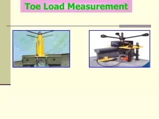
Toe Load measuring device • Toe load measuring device is used to determine the toe load of elastic rail clips during service in the field. • There are two type of toe load measuring devices used on Indian Railways • 1) Mechanical Type • 2) Electronic Type
Mechanical Type……… • The toe load measuring device consists of a pre-calibrated helical spring having a steel pointer attached to a lever arrangement through a link hanger for gripping elastic rail clip. • When the spring is compressed by turning a rotating handle at the top of the device, the toe of the clip gets pulled up and compression of the spring causes a pointer to indicate displacement on a graduated scale.
Mechanical Type……… • The Toe load (in Kg) exerted by the spring on the toe of the clip is measured by multiplying the displacement of the pointer and the spring constant. The device is supported on three legs, two resting on the sleeper and one on the rail head.
Salient features : • (i) Weight (max.) : 12 Kg • (ii) Capacity of the spring to measure toe load : 1400 Kg • (iii) Material of the main spring : Silico-manganese spring steel conforming to Grade 55 of IS : 3195 – 1992.
Operation • Place the device with one leg resting on the rail top and the other two legs resting on the sleeper surface. • Adjust horizontally the base plate by means of the nut of levelling leg. • Turn the handle continuously till air gap is created between rail flange/top of liner and toe of clip. Introduce a filler gauge of 0.1 mm thickness in the air gap created between the toe of the clip and the rail flange / top surface of liner .
Operation….. • The handle is then turned anticlockwise so that the filler gauge comes under a normal pressure. Turn the handle again clockwise and simultaneously pull out the filler gauge. The filler gauge when moves indicates the lifting of toe of clip. • At this stage note down the reading on the graduated scale which when multiplied by the spring constant gives the toe load exerted by clip on the rail foot.
Following precautions shall be observed during operation: • There shall be no oily substance on the surface of tongs so as to prevent slippage during operation. • Steel grip shall be engaged firmly to the clip to avoid the slippage on the application of load. • Longer portion of the steel grip shall be away from rail web. • Base plate shall be horizontal. • Link hanger shall be vertical to the toe of the clip. • Operator shall not lean over the device.
Electronic toe load measuring device has a load cell of 2000 kg capacity and an LCD panel integrated with suitable electronic circuitry. This device has got a lever arrangement attached to it in order to grip the toe of a elastic rail clip. When the load cell is compressed by turning a rotating handle, the elastic rail clip gets pulled up. The force applied on load cell is converted into load (in kg.) and displayed directly on LCD.
Salient Features: (i) Load cell capacity : 2000 Kg. (ii) Operating temperature : -5 to +70 0C (iii) Measurement accuracy : + 0.5% of rated capacity. (iv) Display : 8 or 16 character alphanumeric display (v) Sensitivity : Fast return to zero (vi) Operating Source : Rechargeable battery Pack.
Testing procedure • Put the measuring unit of the electronic toe load device to ‘ON’ position for few minutes before measuring the toe load of an elastic rail clip. • Place the device on its three supporting legs with one resting on the top of the rail head and the other two resting on the sleeper. • Bring the base plate in horizontal position by means of the levelling leg provided for adjustment of the three legs. • Engage the tong to the elastic rail clip keeping longer portion of the tong away from rail web.
Turn handle clock-wise to compress the load cell and pull the hanger. The toe of elastic rail clip will get pulled up. • Continue to turn the handle until the toe leaves contact with the liner/ rail foot. Feeler gauge of gap sensing device having thickness of 0.05-0.1 mm is inserted below the toe of clip. The handle is then turned anti clock-wise so that the feeler gauge comes under normal pressure. Turn handle clock-wise again and simultaneously the gap-sensing device is pulled out gently. When the feeler gauge moves out , it indicates the incipient point of lifting of toe of elastic rail clip and at the same time sensing device automatically freezes the toe load reading on LCD. At this stage, the reading displayed on LCD panel is the measured toe load of the elastic rail clip.
Following precautions shall be observed during working: • The operator shall be fully conversant with the using, maintenance and trouble shooting of the device. • The device shall be properly placed on its three legs and the base plate shall be kept horizontal before measuring the toe load. • No extra effort shall be utilized on the gap sensing instrument during pulling out of the feeler gauge. • Feeler gauge shall be correctly engaged to the clip to avoid slippage. • The operator shall not lean over the device. • It shall be ensured that the longer portion of the steel grip shall be away from rail web. • Link hanger shall be vertical to the toe of the clip.