Download
1 / 42
420 likes | 472 Vues
Discover robust encoding and framing techniques to ensure reliable data transmission. Explore NRZ, Manchester, and more methods for error detection. Learn about SONET framing for clock-based transmission.

E N D
EECS 122: EE122: Error Detection and Reliable Transmission Computer Science Division Department of Electrical Engineering and Computer Sciences University of California, Berkeley Berkeley, CA 94720-1776
Overview • Encoding • Framing • Error detection & correction
Encoding • Goal: send bits from one node to another node on the same physical media • This service is provided by the physical layer • Problem: specify a robust and efficient encoding scheme to achieve this goal Signal Adaptor Adaptor Adaptor: convert bits into physical signal and physical signal back into bits
Assumptions • Use two discrete signals, high and low, to encode 0 and 1 • The transmission is synchronous, i.e., there is a clock used to sample the signal • In general, the duration of one bit is equal to one or two clock ticks
NRZ (non-return to zero) Non-Return to Zero (NRZ) • 1 high signal; 0 low signal • Disadvantages: when there is a long sequence of 1’s or 0’s • Sensitive to clock skew, i.e., difficult to do clock recovery • Difficult to interpret 0’s and 1’s (baseline wander) 0 0 1 0 1 0 1 1 0 Clock
NRZI (non-return to zero intverted) Non-Return to Zero Inverted (NRZI) • 1 make transition; 0 stay at the same level • Solve previous problems for long sequences of 1’s, but not for 0’s 0 0 1 0 1 0 1 1 0 Clock
Manchester Manchester • 1 high-to-low transition; 0 low-to-high transition • Addresses clock recovery and baseline wander problems • Disadvantage: needs a clock that is twice as fast as the transmission rate 0 0 1 0 1 0 1 1 0 Clock
4-bit/5-bit • Goal: address inefficiency of Manchester encoding, while avoiding long periods of low or high signals • Solution: • Use 5 bits to encode every sequence of four bits such that no 5 bit code has more than one leading 0 and two trailing 0’s • Use NRZI to encode the 5 bit codes 4-bit 5-bit 4-bit 5-bit • 1000 10010 • 1001 10011 • 1010 10110 • 1011 10111 • 1100 11010 • 1101 11011 • 1110 11100 • 1111 11101 • 0000 11110 • 0001 01001 • 0010 10100 • 0011 10101 • 0100 01010 • 0101 01011 • 0110 01110 • 1111 01111
Overview • Encoding • Framing • Error detection & Correction
Framing • Goal: send a block of bits (frames) between nodes connected on the same physical media • This service is provided by the data link layer • Use a special byte (bit sequence) to mark the beginning (and the end) of the frame • Problem: what happens if this sequence appears in the data payload?
Byte-Oriented Protocols: Sentinel Approach 8 8 • STX – start of text • ETX – end of text • Problem: what if ETX appears in the data portion of the frame? • Solution • If ETX appears in the data, introduce a special character DLE (Data Link Escape) before it • If DLE appears in the text, introduce another DLE character before it • Protocol examples • BISYNC, PPP, DDCMP STX Text (Data) ETX
Byte-Oriented Protocols: Byte Counting Approach • Sender: insert the length of the data (in bytes) at the beginning of the frame, i.e., in the frame header. • Receiver: extract this length and decrement it every time a byte is read. When this counter becomes zero, we are done.
Bit-Oriented Protocols 8 8 Start sequence End sequence • Both start and end sequence can be the same • E.g., 01111110 in HDLC (High-level Data Link Protocol) • Sender: inserts a 0 after five consecutive 1s • Receiver: when it sees five 1s makes decision on the next two bits • if next bit 0 (this is a stuffed bit), remove it • if next bit 1 (sixth 1 in a row), look at the next bit • If 0 this is end-of-frame (receiver has seen 01111110) • If 1 this is an error, discard the frame (receiver has seen 01111111) Text (Data)
Clock-Based Framing (SONET) • SONET (Synchronous Optical NETwork) • Example: SONET ST-1: 51.84 Mbps
Clock-Based Framing (SONET) • First two bytes of each frame contain a special bit pattern that allows to determine where the frame starts • No bit-stuffing is used • Receiver looks for the special bit pattern every 810 bytes • Size of frame = 9x90 = 810 bytes Data (payload) overhead SONET STS-1 Frame 9 rows 90 columns
Clock-Based Framing (SONET) • Details: • Overhead bytes are encoded using NRZ • To avoid long sequences of 0’s or 1’s the payload is XOR-ed with a special 127-bit patter with many transitions from 1 to 0 • Duration of a frame is 51.84 usec (51.84 Mbps for STS-1)
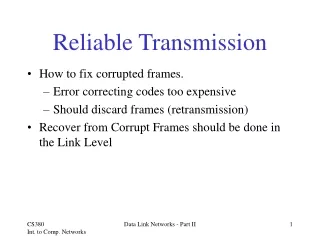
High Level View • Goal: transmit correct information • Problem: bits can get corrupted • Electrical interference, thermal noise • Solution • Detect errors • Recover from errors • Correct errors • Retransmission(already done this!)
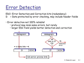
Error Detection (and Correction) • Problem: detect bit errors in packets (frames) • Solution: add extra bits to each packet • Goals: • Reduce overhead, i.e., reduce the number of added bits • Increase the number and the type of bit error patterns that can be detected • Examples: • Two-dimensional parity • Checksum • Cyclic Redundancy Check (CRC) • Hamming Codes
Overview • Two-dimensional Parity • Checksum • Cyclic Redundancy Check • Hamming Codes
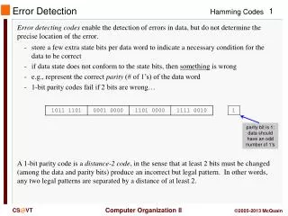
Two-dimensional Parity • Add one extra bit to a 7-bit code such that the number of 1’s in the resulting 8 bits is even (or odd for odd parity) • Add a parity byte for the packet • Example: five 7-bit character packet, even parity 0110100 1 1011010 0 0010110 1 1110101 1 1001011 0 1000110 1
odd number of 1’s How Many Errors Can you Detect? • All 1-bit errors • Example: 0110100 1 1011010 0 0000110 1 error bit 1110101 1 1001011 0 1000110 1
How Many Errors Can you Detect? • All 2-bit errors • Example: 0110100 1 1011010 0 0000111 1 error bits 1110101 1 1001011 0 1000110 1 odd number of 1’s on columns
How Many Errors Can you Detect? • All 3-bit errors • Example: 0110100 1 1011010 0 0000111 1 error bits 1100101 1 1001011 0 1000110 1 odd number of 1’s on column
How Many Errors Can you Detect? • Most 4-bit errors • Example of 4-bit error that is not detected: 0110100 1 1011010 0 0000111 1 error bits 1100100 1 1001011 0 1000110 1 How many errors can you correct?
Overview • Two-dimensional Parity • Checksum • Cyclic Redundancy Check • Hamming Codes
Checksum • Sender: add all words of a packet and append the result (checksum) to the packet • Receiver: add all words of a packet and compare the result with the checksum • Can detect all 1-bit errors • Example: Internet checksum • Use 1’s complement addition
-15+16 = 1 00000000 1 + 1 00000001 1’s Complement Revisited • Negative number –x is x with all bits inverted • When two numbers are added, the carry-on is added to the result • Example: -15 + 16; assume 8-bit representation 15 = 00001111 -15 = 11110000 + 16 = 00010000
Overview • Two-dimensional Parity • Checksum • Cyclic Redundancy Check • Hamming Codes
Cyclic Redundancy Check (CRC) • Represent a (n+1)-bit message as an n-degree polynomial M(x) • E.g., 10101101 M(x) = x7 + x5 + x3 + x2 + x0 • Choose k-degree polynomial C(x) as divisor • Compute reminder R(x) of M(x)*xk / C(x), i.e., compute A(x) such that M(x)*xk = A(x)*C(x) + R(x), where degree(R(x)) < k • Let T(x) = M(x)*xk – R(x) = A(x)*C(x) • Then • T(x) is divisible by C(x) • First n coefficients of T(x) represent M(x)
Cyclic Redundancy Check (CRC) • Sender: • Compute and send T(x), i.e., the coefficients of T(x) • Receiver: • Let T’(x) be the (n+k)-degree polynomial generated from the received message • If C(x) divides T’(x) no errors; otherwise errors • Note: all computations are modulo 2
Arithmetic Modulo 2 • Like binary arithmetic but without borrowing/carrying from/to adjacent bits • Examples: • Addition and subtraction in binary arithmetic modulo 2 is equivalent to XOR 101 + 010 111 101 + 001 100 1011 + 0111 1100 101 - 010 111 101 - 001 100 1011 - 0111 1100
Some Polynomial Arithmetic Modulo 2 Properties • If C(x) divides B(x), then degree(B(x)) >= degree(C(x)) • Subtracting/adding C(x) from/to B(x) modulo 2 is equivalent to performing an XOR on each pair of matching coefficients of C(x) and B(x) • E.g.: B(x) = x7 + x5 + x3 + x2 + x0 (10101101) C(x) = x3 + x1 + x0 (00001011) B(x) - C(x) = x7 + x5 + x2 + x1 (10100110)
R(x) Example (Sender Operation) • Send packet 110111; choose C(x) = 101 (k = 2) • M(x)*xK 11011100 • Compute the reminder R(x) of M(x)*xk / C(x) • Compute T(x) = M(x)*xk - R(x) 11011100 xor 1 = 11011101 • Send T(x) 101) 11011100 101 111 101 101 101 100 101 1
101) 11001101 101 110 101 111 101 101 101 1 R’(x) Example (Receiver Operation) • Assume T’(x) = 11011101 • C(x) divides T’(x) no errors • Assume T’(x) = 11001101 • Reminder R’(x) = 1 error! • Note: an error is not detected iff C(x) divides T’(x) – T(x)
CRC Properties • Detect all single-bit errors if coefficients of xk and x0 of C(x) are one • Detect all double-bit errors, if C(x) has a factor with at least three terms • Detect all number of odd errors, if C(x) contains factor (x+1) • Detect all burst of errors smaller than k bits
Overview • Two-dimensional Parity • Checksum • Cyclic Redundancy Check • Hamming Codes
Code words • Combination of the n payload bits and the k check bits as being a n+k bit code word • For any error correcting scheme, not all n+k bit strings will be valid code words • Errors can be detected if and only if the received string is not a valid code word • Example: even parity check only detects an odd number of bit errors
Hamming Distance • Given code words A and B, the Hamming distance between them is the number of bits in A that need to be flipped to turn it into B • E.g., H(011101,000000) = 4 • If all code words are at least d Hamming distance apart, then up to d-1 bit errors can be detected Richard W. Hamming (1915-1998)
Error Correction • If all the code words are at least a Hamming distance of 2d+1 apart then up to d bit errors can be corrected • Just pick the codeword closest to the one received! • How many bits are required to correct d errors when there are n bits in the payload? • Example: d=1: Suppose n=3. Then any payload can be transformed into 3 other payload strings (e.g., 000 into 001, 010 or 100). • Need at least two extra bits to differentiate between 4 possibilities • In general need at least k ≥ log2(n+1) bits to correct one error • A scheme that is optimal is called a perfect parity code
Perfect Parity Codes • Consider a codeword of n+k bits • b1 b2 b3 b4 b5 b6 b7 b8 b9 b10 b11… • Parity bits are in positions 20, 21, 22 ,23 ,24… • b1b2b3 b4b5 b6 b7 b8b9 b10 b11… • A parity bit in position 2h, checks all data bits bp such that if you write out p in binary, the hth place in p’s binary representation is an one
Example: (7,4)-Parity Code • n=4, k=3 • Corrects one error • log2(1+n) = 2.32 k = 3, perfect parity code • data payload = 1010 • For each error there is a unique combination of checks that fail • E.g., 3rd bit is in error,:1000 both b2 and b4 fail (single case in which only b2 and b4 fail)
Summary • Encoding – specify how bits are transmitted on the physical media • Challenge – achieve • Efficiency – ideally, bit rate = clock rate • Robust – avoid de-synchronization between sender and receiver when there is a large sequence of 1’s or 0’s • Framing – specify how blocks of data are transmitted • Challenge • Decide when a frame starts/ends • Differentiate between the true frame delimiters and delimiters appearing in the payload data