Error Detection
Explore error detection and correction bits, including parity checking, checksums, CRC, and CDMA in the Data Link Layer. Learn how redundancy helps ensure data integrity and reliability.

Error Detection
E N D
Presentation Transcript
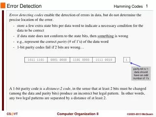
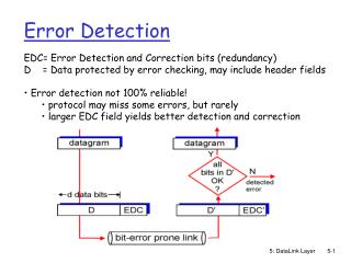
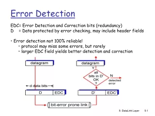
Error Detection • EDC= Error Detection and Correction bits (redundancy) • D = Data protected by error checking, may include header fields • Error detection not 100% reliable! • protocol may miss some errors, but rarely • larger EDC field yields better detection and correction 5: DataLink Layer
Parity Checking Two Dimensional Bit Parity: Detect and correct single bit errors Single Bit Parity: Detect single bit errors 0 0 5: DataLink Layer
Sender: treat segment contents as sequence of 16-bit integers checksum: addition (1’s complement sum) of segment contents sender puts checksum value into UDP checksum field Receiver: compute checksum of received segment check if computed checksum equals checksum field value: NO - error detected YES - no error detected. But maybe errors nonetheless? More later …. Internet checksum Goal: detect “errors” (e.g., flipped bits) in transmitted segment (note: used at transport layer only) 5: DataLink Layer
Checksumming: Cyclic Redundancy Check • view data bits, D, as a binary number • choose r+1 bit pattern (generator), G • goal: choose r CRC bits, R, such that • <D,R> exactly divisible by G (modulo 2) • receiver knows G, divides <D,R> by G. If non-zero remainder: error detected! • can detect all burst errors less than r+1 bits • widely used in practice (ATM, HDCL) 5: DataLink Layer
CRC Example Want: D.2r XOR R = nG equivalently: D.2r = nG XOR R equivalently: if we divide D.2r by G, want remainder R D.2r G R = remainder[ ] 5: DataLink Layer
Code Division Multiple Access (CDMA) • used in several wireless broadcast channels (cellular, satellite, etc) standards • unique “code” assigned to each user; i.e., code set partitioning • all users share same frequency, but each user has own “chipping” sequence (i.e., code) to encode data • encoded signal = (original data) X (chipping sequence) • decoding: inner-product of encoded signal and chipping sequence • allows multiple users to “coexist” and transmit simultaneously with minimal interference (if codes are “orthogonal”) 5: DataLink Layer
d0 = 1 1 1 1 1 1 1 d1 = -1 1 1 1 1 1 1 1 1 1 1 1 1 1 1 1 1 1 1 1 1 1 1 1 1 1 1 - - - - - - - - - - - - - - - - - - - - - - - - - - - - - - - - 1 1 1 1 1 1 1 1 1 1 1 1 1 1 1 1 1 1 1 1 1 1 1 1 1 1 1 1 1 1 1 1 M Di = SZi,m.cm m=1 M d0 = 1 d1 = -1 CDMA Encode/Decode channel output Zi,m Zi,m= di.cm data bits sender slot 0 channel output slot 1 channel output code slot 1 slot 0 received input slot 0 channel output slot 1 channel output code receiver slot 1 slot 0 5: DataLink Layer
CDMA: two-sender interference 5: DataLink Layer