Combination Circuits
Combination Circuits. Lesson 7. Combination circuits. Combination or mixed circuits contain both series and parallel connections. Applying Kirchhoff’s Voltage law to a mixed circuit.

Combination Circuits
E N D
Presentation Transcript
Combination Circuits Lesson 7
Combination circuits • Combination or mixed circuits contain both series and parallel connections
Applying Kirchhoff’s Voltage law to a mixed circuit • To analyze a mixed circuit, start by separating the circuit into sections that are connected in parallel and sections that are connected in series.
Applying Kirchhoff’s Voltage law to a mixed circuit • To view a mixed circuit, start by separating the circuit into sections that in series and sections that are connected in parallel. Series Circuit Parallel Circuit
Using this approach of two separate paths, you can think of two independent series circuits. • Source = 40 V, lamp 1 = 10 V, lamp 3 = 20 V. • Find the voltage of lamp 2 and 4. Lamp 2 Lamp 1 Lamp 4 Lamp 3
Use KVL to solve for V2 • What formula do we need to use? • Vsource = V1 + V2 + V3 • 40 V = 10 V + V2 + 20 V • 40 V = 30 V + V2 • V2 = 10 V
Use KVL to solve for V4 • According to KVL, voltages in a parallel circuit are the same. Thus V3 must equal V4 • Vsource = V1 + V2 + V4 • 40 V = 10 V + 10 V + V4 • 40 V = 20 V + V4 • V4 = 20 V
Applying Kirchhoff’s Current Law to a mixed circuit • The current in a series circuit is constant and stays the same as the source current. The current in a parallel circuit is divided along the paths. • Isource= 0.40 A • I3 = 0.10 A • Find I1 and I2 Lamp 2 Lamp 4 Lamp 1 Lamp 3
What is the formula for current in a series circuit? • Iseries= I1 = I2 • 0.40 A = I1 = I2 • Therefore I2 = 0.40 A
The amount of current entering a junction is equal to the amount of current exiting a junction. • What is the formula used to find current in a parallel circuit? • Iparallel = I3 + I4 • 0.40 A = 0.10 A + I4 • I4 = 0.30 A
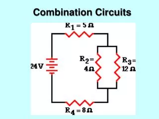
R1 = 12 Ω R3 = 50 Ω R2 = 75 Ω R4 = 30 Ω R5 = 18 Ω Resistance in a mixed Circuit • Calculate the equivalent resistance for the circuit diagram below
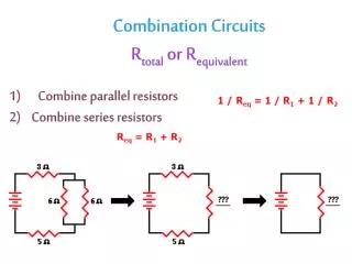
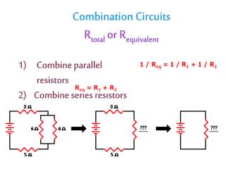
R1 = 12 Ω R3 = 50 Ω R2 = 75 Ω R4 = 30 Ω R5 = 18 Ω Resistance in a mixed Circuit • Step 1. Divide the circuit into series and parallel parts. Parallel
Step 2. Find the equivalent of the parallel part of the circuit.
R1 = 12 Ω Rparallel = 15 Ω R5 = 18 Ω Step 3. Redraw the circuit using the equivalent resistance from step 2.
Step 4. Solve to determine the equivalent resistance of the remaining series circuit. Let the equivalent resistance for the complete circuit be Rtotal: What is the formula to calculate resistance in a series circuit • Rtotal = R1 + Rparallel + R5 • Rtotal = 12 Ω + 15 Ω + 18 Ω • Rtotal = 45 Ω • Therefore, the equivalent resistance is 45 Ω
R2 R1 R3 R5 R4 Questions • What is the total resistance of the mixed circuit shown to the right, note that each resistor has a resistance of 5.0 Ω. T (4)
R1 R3 R2 R5 R4 Questions • What is the total resistance of the mixed circuit shown to the right, note that each resistor has a resistance of 5.0 Ω. T (4)
Draw the following circuit and calculate the unknown in each situation. C (1) • A 6.0 Ω resistor (R1) is in series with a power source, two more resistors (R2 = 20 Ω and R3 = 30 Ω) are in parallel to each other and in series with R1. T (2) • If the power source was 9.0 V, what is the voltage drop across each resistor? T (3)