
Polarization and Diffraction
E N D
Presentation Transcript
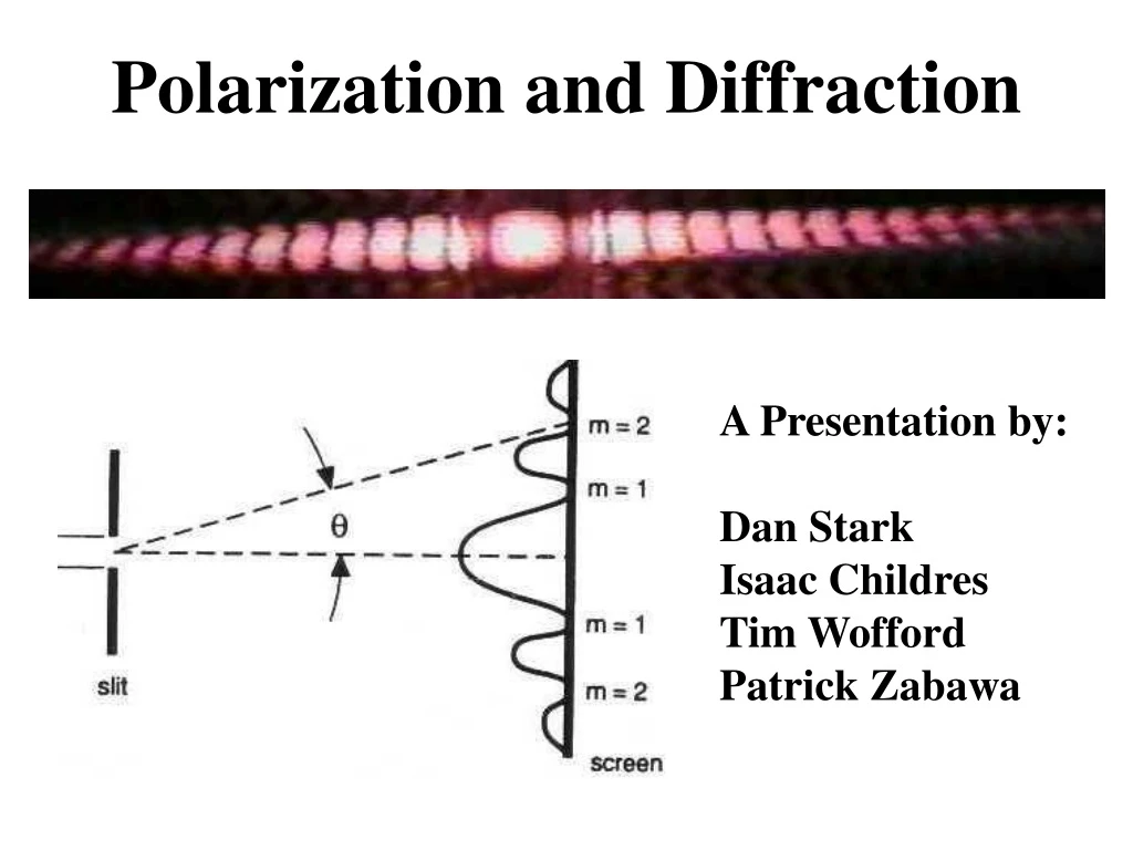
Polarization and Diffraction A Presentation by: Dan Stark Isaac Childres Tim Wofford Patrick Zabawa
Light Sensor Light sensor is mounted on rotary motion sensor Laser and Slit Rotary motion sensor mounted on linear motion accessory which is mounted at other end of track Rotary Motion Sensor Laser and slit mounted 3 cm apart at one end of track Track Linear Motion Accessory Experimental Setup for Diffraction Procedure: • Assemble track, placing neutral density filter(s) between laser and slit in order to prevent saturation of light sensor • Connected sensors to the computer using a breakout box • Took data using Data Studio and passing the light sensor across the linear motion accessory
Fraunhofer Approximation: Where Single Slit Diffraction Theory Electric field at a point due to a slit segment dx Amplitude of incident wave
Solve numerically. I(0) 1 0.8 0.6 FWHM – 2.78 β 0.4 0.2 β -6 -4 -2 2 4 6 Full-Width at Half Max (FWHM) Full width at half max of the envelope is β 2.783114. So as d increases, the peak sharpens.
Results: Single Slit Diffraction Patterns (Plastic) Normalized Light Intensity (%) Position (m)
Results: Single Slit Diffraction Patterns (Razor) Normalized Light Intensity (%) Position (m)
A study of the slight interference pattern observed at the peak of single slit diffraction The Problem: When sending light through a medium in order to accomplish single slit diffraction, we find a slight aberration at the peak Plastic medium (Pasco instrument) No medium (razor blades) Normalized Light Intensity (%) Normalized Light Intensity (%) Position (m) Position (m)
Light comes in at an angle slightly different than zero As it passes through the medium, some transmits and some reflects Note: Rays after the slit represent diffraction patterns, which will have some interference with each other The reflected light will reflect again and eventually come out at some different point, resembling a double slit experiment What’s going on? Given that this only happens when the light travels through a medium, we can only assume the aberration has something to do with the reflection that occurs when light moves from one medium to another.
We performed similar single slit experiments with a piece of glass 2.33mm thick and two pieces of black tape Exploratory Experiment We find “a” to be 0.03m, a slit separation comparable to our other experiments We can find the slit separation, a, based on this equation. If m=1, then y=0.25m, wavelength=670nm and D=1.024m
Experimental Results At some minute angle, say 1 degree, given a width of 2.33mm, which must be traveled twice by the reflected light, we would have an effective double slit separation of 0.08mm, which is on the same order of magnitude as our double slit experiments. Normalized Light Intensity (%) Position (m) Given these conditions, a dip can be observed
Experimental Results, cont. Given a larger angle, say 15 degrees, the effective double slit separation would increase to 1.25mm and the dip would disappear due to the overly large separation. Normalized Light Intensity (%) Position (m) Given these conditions, less of a dip can be observed
I(0) Where • Envelope • High Frequency • Wave group Where and . β Multiple Slit Diffraction Theory Consider A system with N slits of width d separated by a distance a, E can be written as: 1 0.8 0.6 0.4 Note: N = 2, α = β 0.2 6 -6 -4 -2 2 4
Results: Double Slit Diffraction Patterns 0.04 mm slit size – 0.25 and 0.5 slit separations Normalized Light Intensity (%) Position (m)
Results: Double Slit Diffraction Patterns 0.04 mm slit size – 0.25 mm slit separation 0.08 mm slit size – 0.25 mm slit separation Normalized Light Intensity (%) Normalized Light Intensity (%) Position (m) Position (m)
Results: Multiple Slit Diffraction Patterns 0.04 mm slit size – 0.125 slit separation Normalized Light Intensity (%) Position (m)
Light Sensor Aperture Disk Polarizers Laser Rotary Motion Sensor Optics Bench Experimental Setup for Polarization Procedure: • Assemble track, placing neutral density filter(s) between laser and 1st polarizer in order to prevent saturation of light sensor • Connected sensors to the computer using a breakout box • Took data using Data Studio and rotating the 2nd polarizer connected to the rotary motion sensor
Jones matrix for linear polarizer with a transmission axis making an angle θ with x-axis Where impedance of the medium. Where R(θ) is the rotation matrix Jones matrix, characterizes polarization device Transmits only x-component of wave, a linear polarizer Polarization Theory Jones vector with
Experimental Results of Malus’ Law This experiment uses two polarizers, one that polarizes the light initially and one that varies to show angular dependence. Normalized Light Intensity (%) Angular Position (Degrees)
Polarization of the Laser This data was taken with one polarizer to show that the laser light is already almost linearly polarized. (Basically we did not need the first polarizer) Normalized Light Intensity (%) Angular Position (Degrees)
Resources http://www.pa.msu.edu/courses/1997spring/PHY232/lectures/interference/oneslit.html http://rhs.rocklin.k12.ca.us/gclarion/physics2/chapter19/singleslit.htm http://www.mu.edu/courses/phys/matthysd/Lab0122.htm http://bednorzmuller87.phys.cmu.edu/demonstrations/optics/interference/demo321.html http://www.colorado.edu/physics/phys2020/phys2020_f98/lab_manual/Lab5/lab5.html http://rhs.rocklin.k12.ca.us/gclarion/apphysics/chapter27/diffractioninterference.htm http://www.ccmr.cornell.edu/~muchomas/P214/Notes/Interference/node19.html http://www3.ltu.edu/~s_schneider/physlets/main/doubleslitintensity.shtml http://electron9.phys.utk.edu/optics421/modules/m5/Diffraction.htm http://hyperphysics.phy-astr.gsu.edu/hbase/phyopt/mulslid.html Saleh, B. E. A. and Teich, M. C. Fundamentals of Photonics. John Wiley and Sons, Inc.: New York: New York. 1991.