Download
1 / 53
530 likes | 556 Vues
Learn about recognizing traumatic aortic injuries through chest radiographs, treatment options, diagnostic algorithms, and outcomes. Understand the mechanisms and clinical features associated with this devastating injury.

E N D
Traumatic Aortic Injuries: Recognition and Treatment” Melanie Flores DO PGY5 MelhemGhaleb MD AryaBagherpour DO PGY2 Department of Radiology Texas Tech University Health Sciences Center
Learning Objectives • Illustrate the expected lines and stripes seen on initial trauma chest radiographs. • Discuss abnormal imaging features on chest radiography which suggest traumatic aortic injury (TAI). • Discuss treatment benefits, risks and outcomes of endovascular TAI repair versus traditional surgical treatment. • Propose a diagnostic algorithm to facilitate accurate diagnosis and appropriate management.
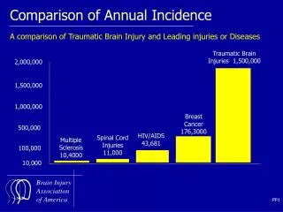
Traumatic Aortic Injuries (TAI) • Blunt rupture of the thoracic aorta is devastating, and most patients die at the time of injury. • Although aortic trauma accounts for less than 0.5% of all trauma admissions, it constitutes the second leading cause of trauma-related death, second only to head injury. • Only about 15% of TAI survive long enough to get to the hospital. • Of these survivors, 99% will die without surgical intervention. • 15% survive only the first hour • 30% die within 6 hours • 49% within 24hrs • 72% within 8 days • 90% within 4 months
The Challenge of TAI • The challenge of this injury is that although the injury is uncommon, the suggestive mechanism of injury is extremely frequent. • Emergency physicians, trauma surgeons and radiologists must combine: • Understanding of the mechanism of injury • Knowledge of the suggestive signs and symptoms • Accurate interpretation of the primary survey chest radiograph
Mechanism of Injury • Typical mechanism causing TAI is blunt deceleration. • Shear, torsion, and hyperflexion lead to a tearing phenomenon at the aortic isthmus where the relatively mobile arch becomes fixed to the posterior mediastinum and pleura. • TAI occurs at • Isthmus (IIC) 70-90% • Ascending aorta/proximal arch (I to IIB) 10-15% • Mid-descending aorta (IIIA to IIIB) 5-10%
Mechanism of Injury • Most important factor in establishing the diagnosis • Falls > 10 feet • Motor vehicle crashes at speeds > 30 mph • Unrestrained drivers • Ejected passengers • Pedestrians struck by motor vehicles • Severe crush injuries
Clinical Features • Symptoms: • Chest pain, dyspnea, back pain, hoarseness, dysphagia, cough • Signs: • Anterior chest wall contusion, unexplained hypotension, upper limb hypertension, or acute coarctation syndrome, differences in pulse amplitude, and a systolic murmur audible over the base of the heart or between the scapulae. • 30% of TAI patients will have no external signs of injury to the chest • 75% will have fractures of bones other than ribs thus distracting attention away from the chest injury • With significant force necessary to create TAI, other associated injuries are common. • Head injuries • Solid organ injuries • Pulmonary contusions • Long-bone fractures
Chest Radiographs • Information is derived from the configurations and interrelationships of the anatomic structures in the lung, mediastinum, and pleura. • Forms the basis of the “lines and stripes” concept, which plays a valuable role in establishing a diagnosis before proceeding to CT. • Inability to recognize that a chest radiograph is abnormal owing to displacement of one of these lines or stripes may lead to failure to request a potentially valuable CT or proceed to intervention promptly.
Lines and Stripes • Lines typically measure less than 1 mm in width and formed by air, typically within the lung, outlining thin intervening tissue on both sides. • Anterior junction line • Posterior junction line • Stripes are thicker lines formed by air outlining thicker intervening tissue. • Left paratracheal stripe • Right paratracheal stripe • Posterior tracheal stripe • Interfaces are formed when structures of different densities come in contact with one another. • Right and left paraspinal lines • Azygoesophageal recess
Anterior Junction Line • Formed by the apposition of the visceral and parietal pleura of the anteromedial aspects of the lungs with a small amount of intervening fat. • Oblique line crossing the superior two-thirds of the sternum from upper right to lower left. • May be seen in 24-57% of frontal chest radiographs • Obliteration or abnormal convexity of the line suggests underlying anterior mediastinal disease such as • Aortic injury • Thyroid masses • Lymphadenopathy • Neoplasms • Thymic masses • Lipomatosis • Volume loss and hyperinflation
Anterior Junction Line Figure 1. Illustration (a) and frontal chest radiograph (b) show a normal anterior junction line (black lines in a, arrows in b) coursing obliquely from the upper right to the lower left over the superior two-thirds of the sternum. CT scan demonstrates a normal anterior junction line (arrow) formed by the apposition of the visceral and parietal pleura of the lungs with intervening mediastinal fat. Gibbs J M et al. Radiographics 2007;27:33-48
Anterior Junction Line Figure 2. Abnormal appearing anterior junction line in a patient who had undergone a right middle lobectomy. (a) Frontal chest radiograph shows the anterior junction line (arrows) displaced to the right. Note also the volume loss in the right lung as demonstrated by elevation of the right hemidiaphragm. (b) CT scan helps confirm rightward displacement of the anterior junction line
Posterior Junction Line • Formed by the apposition of the visceral and parietal pleura of the posteromedial portion of the lungs posterior to the esophagus and anterior to the 3-5th thoracic vertebrae. • Straight or mildly leftward convex line, typically projecting through the trachea. More cranial extension than the AJL, and is seen above the clavicles. • Seen on 32% of chest radiographs • Abnormal bulging or convexity suggests a posterior mediastinal abnormality such as • Esophageal masses • Lymphadenopathy • Aortic disease • Neurogenic tumors
Posterior Junction Line Figure 3. Illustration (a) and frontal chest radiograph (b) demonstrate a normal posterior junction line (black lines in a, arrows in b) as a straight line projecting through the trachea and extending above the clavicles. (c) CT scan demonstrates a normal posterior junction line (arrow), which lies posterior to the esophagus and is formed by the apposition of the visceral and parietal pleura of the lungs anterior to the thoracic vertebrae.
Right Paratracheal Stripe • Visceral and parietal pleura of the right upper lobe come in contact with the right lateral border of the trachea and the intervening mediastinal fat, air within the right lung and trachea outline these entities. • Begins superiorly at the level of the clavicles and extends inferiorly to the right tracheobronchial angle at the level of the azygos arch. • Most commonly seen mediastinal line or stripe, 97% of chest radiographs • Widening or abnormal contour caused by • Paratracheal lymphadenopathy • Thyroid or parathyroid neoplasms • Tracheal carcinoma or stenosis • Pleural effusion or thickening
Right Paratracheal Stripe Figure 4. Illustration (a) and frontal chest radiograph (b) demonstrate a normal right paratracheal stripe (black line in a, arrows in b). CT (c) scan shows that the right paratracheal stripe (arrow) is formed by air within the right upper lobe and trachea outlining the right lateral tracheal wall, right upper lobe pleura, and intervening soft tissues.
Right Paratracheal Stripe Figure 5. Abnormal right paratracheal stripe caused by a large ectopic parathyroid adenoma in a 52-year-old man. (a) Frontal chest radiograph demonstrates widening of the right paratracheal stripe (arrow). (b) CT scan helps confirm a large right paratracheal mass (arrow) with diffuse osteopenia from primary hyperparathyroidism.
Left Paratracheal Stripe • Formed by contact between the left upper lobe and either the mediastinal fat adjacent to the left tracheal wall or the left tracheal wall itself. • Stripe extends superiorly from the aortic arch to join with the reflection from the left subclavian artery. • Visible on 21-31% of chest radiographs • Abnormal contour or widening is seen in • Large left-sided pleural effusions • Neoplasm • Mediastinal hematoma
Left Paratracheal Stripe Figure 6. Illustration (a) and frontal chest radiograph (b) demonstrate a normal left paratracheal stripe (black line in a, arrows in b) extending from the aortic arch to join with the reflection from the left subclavian artery superiorly.
Left Paratracheal Stripe Figure 7. Abnormal-appearing left paratracheal stripe in a 47-year-old patient with metastatic thyroid carcinoma. (a) Frontal chest radiograph demonstrates widening of the left paratracheal stripe (arrows) with mass effect on the trachea. (b) CT scan reveals a large thyroid mass (arrow) and associated supraclavicular
Aortic-Pulmonary Stripe • A mediastinal reflection or interface formed by the pleura of the anterior left lung coming in contact with and tangentially reflecting over the mediastinal fat anterolateral to the left pulmonary artery and aortic arch. • Straight or mildly convex, crossing laterally over the aortic arch and the main pulmonary artery. • Abnormal appearance or increased convexity laterally caused by: • Thryoid or thymic masses • Prevascular lymphadenopathy • Vascular injury
Aortic-Pulmonary Stripe Figure 8. Illustration (a) and frontal chest radiograph (b) demonstrate a normal aortic-pulmonary stripe (black line in a, arrows in b) as a straight interface crossing the aortic arch and the main pulmonary artery. CT (c) scan shows a normal aortic-pulmonary stripe (arrows) formed by the anterior left lung contacting and tangentially reflecting over the mediastinal fat antero-lateral to the left pulmonary artery and aortic arch.
Aortic-Pulmonary Stripe Figure 9. Abnormal-appearing aortic-pulmonary stripe in a 42-year-old patient with lymphoma. (a) Frontal chest radiograph demonstrates abnormal contour of the aortic-pulmonary stripe (arrows). (b) CT scan shows anterior mediastinallymphadenopathy (arrows) within the prevascular
Aortopulmonary Window • A mediastinal space seen as an interface, lies posterior to the previously discussed aortic-pulmonary stripe. • Lateral border forms the interface by the left lung and pleura coming in contact with the aortic arch and extending inferiorly to contact the left pulmonary artery. Left lung extends into the space connecting the aortic arch and the left pulmonary artery, thereby forming the normal concave reflection. • Convex contour of the AP window is abnormal. • Aortic aneuryms and injury • Prominent mediastinal fat • Lymphadenopathy • Bronchial artery aneurysms • Nerve sheath tumors
Aortopulmonary Window Figure 10. Frontal chest radiograph demonstrates a normal AP window as a shallow concave interface (*) between the aorta and the pulmonary artery. Note the normal aortic-pulmonary stripe (arrows) and its relation to the AP window. CT scan shows the normal AP window (*). The concave interface seen in the chest radiograph actually represents the lateral border (arrow) of the AP window formed by the left lung and pleura contacting the aortic arch and extending to the pulmonary artery.
Aortopulmonary Window Figure 11. Abnormal-appearing AP window in a 64-year-old patient with bronchogenic carcinoma. (a) Frontal chest radiograph demonstrates an abnormal bulge in the AP window (arrow). Thickening of the right paratracheal stripe (*) is also noted, along with left lower lobe consolidation and left pleural effusion. (b) CT scan shows a significant soft-tissue mass within the AP window and subcarinal space, a finding that is compatible with metastatic lymphadenopathy. Lymphadenopathy in the paratracheal region was also noted, accounting for the thickened right paratracheal stripe.
Right Paraspinal Line • Formed by the right lung and pleura coming in tangential contact with the posterior mediastinal soft tissues. • Line appears straight and typically extends from the 8th to 12th vertebral levels. • 23% of chest radiographs • May be displaced laterally from • Osteophytes • Mediastinal fat • Mediastinal hematoma • Mass • Extramedullary hematopoiesis
Right Paraspinal Line Figure 12. Illustration (a) and frontal chest radiograph (b) demonstrate a normal right paraspinal line (black line in a, arrows in b) as a thin straight line extending lateral to the thoracic spine. CT scan shows normal right and left paraspinal lines (arrows) formed by the lungs and pleura contacting the posterior mediastinal soft tissues.
Right Paraspinal Line Figure 13. Abnormal-appearing right paraspinal line in a 27-year-old patient who had sustained traumatic injury. (a) Frontal chest radiograph demonstrates an abnormal bulge in the right paraspinal line inferiorly (arrows). (b) CT scan reveals a large mediastinal hematoma (arrow) from multiple right-sided transverse process fractures of the thoracic spine and an
Left Paraspinal Line • Formed by the tangential contact of the left lung and pleura with the posterior mediastinal fat, left paraspinal muscles, and adjacent soft tissues. • Extends vertically from the aortic arch to the diaphragm, and lies medial to the lateral wall of the descending thoracic aorta. • 41% of chest radiographs • Abnormal contour or displacement caused by • Osteophytes • Tortuosity of the descending aorta • Mediastinal hematoma • Mass • Extramedullary hematopoiesis • Esophageal Varices
Left Paraspinal Line Figure 14. Illustration (a) and frontal chest radiograph (b) demonstrate a normal left paraspinal line (black line in a, arrows in b) as a thin straight line extending from the aortic arch to the diaphragm. The normal left paraspinal line typically lies medial to the lateral wall of the descending thoracic aorta.
Left Paraspinal Line Figure 15. Abnormal-appearing left paraspinal line in a 52-year-old patient with liver cirrhosis and esophageal varices. (a) Frontal chest radiograph reveals a focal lateral bulge in the left paraspinal line (arrow). (b) CT scan shows extensive esophageal varices (arrow), which are responsible for the abnormal contour of the left paraspinal line.
Posterior Tracheal Stripe • Vertical stripe formed by air within the trachea and right lung outlining the posterior tracheal wall and intervening soft tissues. Measures up to 2.5 mm • Abnormal thickening caused by • Acquired vascular lesions • Esophageal lesions • Lymphatic malformations • Mediastinitis • Post-traumatic hematomas
Posterior Tracheal Stripe Figure 16. Lateral chest radiograph demonstrates a normal posterior tracheal stripe (arrows) as a thin vertical stripe posterior to the trachea. CT scan reveals that the posterior tracheal stripe (arrow) is formed by air within the trachea and right lung outlining the posterior tracheal wall and intervening soft tissues.
Posterior Tracheal Stripe Figure 17. Abnormal posterior tracheal stripe in a 49-year-old patient with achalasia. (a) Lateral chest radiograph shows widening of the posterior tracheal stripe (arrows). (b) CT scan demonstrates a dilated esophagus (arrow) filled with food and contrast material.
Mediastinal Abnormalities of TAI • Widened mediastinum • Abnormal aortic outline • Opacification of the AP window • Downward displacement of the left mainstem bronchus • Deviation of trachea to the right of midline • Deviation of NG tube to the right of midline • Widened right paratracheal stripe • 7.3% have normal mediastinum: appears to occur when traumatic pseudoaneurysm is not accompanied by associated mediastinal hemorrhage or hematoma formation.
Other Signs of TAI • Large hemothorax • First and second rib fractures • Left apical cap • Sternal fracture • Posteriorly displaced clavicular fracture • Multiple rib fractures with a crushed chest • Brachial plexus injury • Diminished or absent pulses or blood pressure in upper extremities • Systolic murmur • Palpable supraclavicular hematoma • Unexplained hematoma
Widened Mediastinum • Nonspecific finding but most reliable sign of TAI • Occurs when a TAI changes the contour of the mediastinum or when mediastinal hemorrhage or hematoma occurs. • Mediastinum greater than 8-8.8 cm at the level of the aortic knob in patients with TAI • Supine radiographs in the trauma bay result in magnified mediastinal image which poses a significant problem for interpretation.
M/C Ratio • Seltzer introduced the M/C ratio: ratio of mediastinal width to chest width at the level of the aortic arch. • Concluded that mediastinal widening was sensitive but non-specific. • Defined that an M/C ratio of >0.20 is 100% sensitive but 15% specific • M/C ratio of >0.25 is 95% sensitive and 75% specific • M/C ratio of >0.28 is 75% sensitive and 100% specific • Ultimately, it is not just the actual width but rather the clinicians overall impression of the mediastinal contour.
1 4 6 2 2 7 7 6
So What Next? • Aortography has been the gold standard imaging modality for demonstrating TAI. • Angiographic diagnosis rests on demonstration of an intimal irregularity or filling defect caused by an intimal flap. • Presence of constrast outside the lumen is indicative of a transmural laceration, which may be contained or free extravasation. • 98% specific. • Difficulty with aortography lies in the risk of transferring a potentially unstable patient to the vascular suite for a prolonged period.
Helical or Spiral CT • Gavant’s study in 1995 marked the advent of CECT. • More sensitive than aortography (100% compared to 94%) and only a little less specific (81% compared with 96%) in the detection of aortic injury. • SCT is effective for screening critically injured paitents. • Patients with mediastinal hematoma but not obvious aortic injury on SCT need not undergo aortography. • In 1998, Wicky found chest SCT to be 100% sensitive and 99.8% specific. • Diagnostic SCT is a safe and speedy basis on which to proceed to intervention.
Open Repair • Traditionally, the early morbidity and mortality of TAI established rapid diagnosis along with emergent open aortic repair as standard to prevent rupture and death. • Adding thoracotomy, thoracic aortic clamping, with or without left-heart bypass, and hemodynamic and coagulation fluctuations creates a less than ideal milieu in this population during open repair.
Open Repair • Mortality in 15 to 30% • Spinal cord ischemic complications 5-20% • Stroke 3-8% • Vocal Cord Paralysis 10-15% • Pulmonary complications 10-25%
Endovascular Repair • Endovascular grafting has become more mainstream, if not standard of care, for many aortic disease processes. • Obviates the need for thoracotomy, aortic cross-clamping, and single-lung ventilation. • Avoids any potential for complex distal perfusion or arrest techniques. • Can be accomplished in an hour or less, as opposed to several hours for an open posterolateralthoracotomy with reconstruction. • Performed under less complicated anesthetic methods and possibly even local anesthetic with sedation. • Can be performed just before or immediately after other necessary procedures with minimal compounded stress.
Endovascular Repair • Rosseau et al reviewed 35 patients undergoing open repair and 29 having endograft repair after TAI. • In the open group, operative mortality was 21% and paraplegia occurred in 7%. • No mortality or paraplegia occurred in those undergoing endograft repair.
Endovascular Repair • In 1997, the American Association for the Surgery of Trauma published a 50-center prospective registry of TAI. • 193 patients: 125 endovascular repair; 68 open repair • No difference in systemic complication rate • Significant reduction in gross mortality • Endovascular repair required fewer transfusions and had fewer pneumonias. • No significant paraplegia was discovered (2.95% open versus 0.8% endovascular) • Follow-up averaged 4 years in those with open repair but only ~2 years in those have endovascular repair.
Endovascular Repair Complications • Possible complications • Early endoleak 4.2% • Late endoleak 0.9% • Migration was negligible. • Stent fracture • Shortcomings of endovascular repair: • Appropriate endovascular inventories • Imaging • Around the clock accessiblity • Properly trained endovascular operating team • Current thoracic endografts are really designed for use in degenerative disease, and, as most TAI occur in younger patients, existing graft diameters may not be appropriate for smaller aortas.
Treatment Delay? • It has been shown that treatment delay, to a point where the patient is physiologically better prepared to undergo repair, is beneficial. • Risk of aortic rupture appears to increase after about 1 week, so repair must still be timely • Regardless of repair method, delay beyond 24 hours after injury appeared advantageous. • Of course—a hemodynamically stable patient!