Download
1 / 9
90 likes | 108 Vues
Learn about Leyden jars, dielectric capacitors, charging, voltage, electrostatic fields, circuit behavior, and capacitor connections in electrical systems. Understand capacitor symbols, DC blocking, AC passing, and noise suppression. Discover how capacitors in parallel increase capacitance, while in series decrease it.

E N D
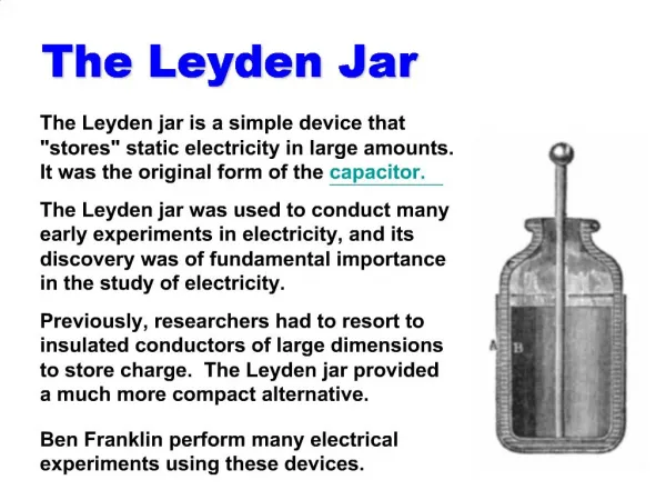
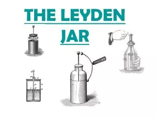
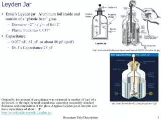
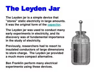
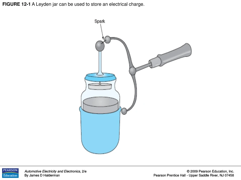
FIGURE 12-1 A Leyden jar can be used to store an electrical charge.
FIGURE 12-2 This simple capacitor, made of two plates separated by an insulating material, is called a dielectric.
FIGURE 12-3 As the capacitor is charging, the battery forces electrons through the circuit.
FIGURE 12-4 When the capacitor is charged, there is equal voltage across the capacitor and the battery. An electrostatic field exists between the capacitor plates. No current flows in the circuit.
FIGURE 12-5 The capacitor is charged through one circuit (top) and discharged through another (bottom).
FIGURE 12-6 Capacitor symbols are shown in electrical diagrams. The negative plate is often shown curved.
FIGURE 12-7 A capacitor blocks direct current (DC) but passes alternating current (AC). A capacitor makes a very good noise suppressor because most of the interference is AC and the capacitor will conduct this AC to groundbefore it can reach the radio or amplifier.
FIGURE 12-8 Capacitors in parallel effectively increase the capacitance.