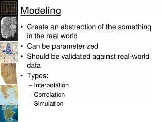
Modeling
Modeling. ECE 417/617: Elements of Software Engineering. Stan Birchfield Clemson University. Overview. Modeling provides abstraction to bridge the gap between High-level (world) Low-level (code) Types of modeling: Analysis modeling Models problem domain (users, world) System modeling


Modeling
E N D
Presentation Transcript
Modeling ECE 417/617:Elements of Software Engineering Stan Birchfield Clemson University
Overview • Modeling provides abstraction to bridge the gap between • High-level (world) • Low-level (code) • Types of modeling: • Analysis modeling • Models problem domain (users, world) • System modeling • Models solution domain (software)
Analysis modeling • Let us first look at modeling the problem domain
Requirements elicitation • It is important to define what the software is supposed to do before • defining how to do it, or • before actually doing it • “The hardest single part of building a software system is deciding what to build.” – Fred Brooks • Requirements elicitation – gathering requirements from users and other stakeholders
Difficulties in specifying requirements • Customers often do not know what they want ... until they see it • Customers often have a poor understanding of the ease or difficulty of implementing different capabilities • The requirements change over time
Steps in gathering requirements • Inception – establish basic understanding of problem • Elicitation – Ask the users what is needed • Elaboration – Refine the model of the S/W functions, features, and constraints • Negotiation – Reconcile conflicts by ranking requirements and discussing priorities • Specification – Final work product describing the function and performance of the S/W • Validation – Examine the specification to ensure that all requirements have been stated unambiguously, inconsistencies have been corrected, etc.
Specifying requirements • Requirements can be specified in a number of ways: • user scenarios • functions and feature lists • analysis models • specification
Traceability table • Captures the relationships between • features and requirements • interfaces and requirements • requirements themselves (dependencies) • etc. aspects requirements
User scenarios • Usage scenarios • identify a thread of usage for the system • enable the S/W team to see how the functions and features will be used by different classes of end users • often called use cases
Use cases • Use case tells a stylized story about how an end-user interacts with the system under a specific set of circumstances • Can be either • narrative text • outline of tasks or interactions • template-based description, or • diagrammatic representation • “A use-case captures a contract...” -- Alistair Cockburn, Writing Effective Use Cases. Addison-Wesley 2000. http://www.usecases.org/
Use case example Use case: Withdraw money Level: User goal (Three levels: Summary, User goal, and Sub-function level) Primary actor: Client Goal in context: To withdraw money from the client’s account Preconditions: User has an account, ATM has power and connectivity Main scenario: • Client inserts card • Client types PIN • Client specifies which account • Client enters amount to withdraw • Money is dispensed • Card is ejected • Client removes card Extensions: 1a. Card is invalid; card is ejected and client notified. 2a. Pin is incorrect; client notified and given no more than two more attempts. 4a. Amount exceeds limit; client notified, repeat step. 7a. Client does not remove card within time limit; card is retracted.
System modeling • Now let us look at modeling the solution domain
Data flow diagram (DFD) • Data flow diagram (DFD) developed in late 1970s • part of Structured Design (one of the earliest methodologies for software development); aka Structured Systems Analysis and Design Method (SSADM), a waterfall method • invented by Larry Constantine, who also developed concepts of coupling and cohesion • DFD is a forerunner of UML and may complement it • Arcs are data; boxes are processes/actions source code executeunittests reviewtestresults test results review decision test plan
Gane and Sarson notation for DFDs • squares – external entities • round rectangles – processes • arrows – data flow • open-ended rectangles – data stores http://www.agilemodeling.com/artifacts/dataFlowDiagram.htm
Data flow diagram (DFD) • DFDs are refined iteratively • Level 0 is context-level DFD; represents s/w as a single bubble with input and output • Level 1 is achieved by expanding the bubble into additional bubbles; perform grammatical parse on narrative describing bubble • Continue refining until each bubble performs specific function; high cohesion • Components: bubbles are processes, boxes are external entities, arrows are data or control objects, and double lines are data stores • Process specification (PSPEC) describes all flow model processes that appear at the final level of refinement. It is a minispec for each transform at the lowest level of a DFD • Program design language description (PDL) is basically pseudocode. One way to represent PSPEC
CRC modeling • Class Responsibility Collaborator (CRC) is a lightweight model • Write on 3”x5” index cards • Used in extreme programming • Can be used for • detailed object-oriented design • conceptual modeling http://www.agilemodeling.com/artifacts/crcModel.htm
CRC example class is collection of objects • two types of collaboration: • request for information • request to do something responsibility is anything a class knows or does http://www.agilemodeling.com/artifacts/crcModel.htm
Creating CRC cards Iteratively • Find classes • Find responsibilities • Define collaborators • Move the cards around http://www.agilemodeling.com/artifacts/crcModel.htm
Unified modeling language (UML) • Several competing object-oriented notations developed in 1980s and 1990s • Rumbaugh and Booch began working together in 1994 at IBM Rational to standardize their notations (OMT and Booch) • Result was Unified Modeling Language (UML) • Rights owned by Object Management Group (OMG), www.omg.org • Good reference: M. Blaha and J. Rumbaugh, Object-Oriented Modeling and Design with UML, 2nd ed.
UML Unified modeling language (UML) includes three models: • class model – structural aspects of system (class diagrams) • state model – temporal, behavioral aspects of system (state diagrams) • interaction model – collaboration of individual objects (use cases, sequence diagrams, and activity diagrams)
A simple problem to provide brief overview of UML switch 1 W 5 V light
1. Use Case Diagram SimpleCircuit FlipOn FlipOff ViewLight User Functionality from user’s point of view
2. Class Diagram Switch Resistor Light Battery 5V Structure of system (objects, attributes, associations, operations)
3. Sequence Diagram Switch Resistor Battery Light User FlipOn() HeatUp() Drain() Shine() Messages between objects
3. Collaboration Diagram User 1. FlipOn() 1.1 HeatUp() Switch Resistor 1.2 Shine() 1.3 Drain() Battery Light More compact, but harder to interpret
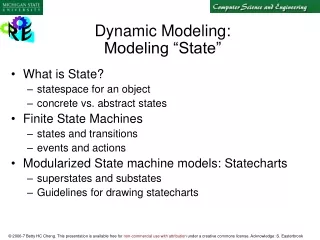
4. Statechart Diagram flipSwitchOn Light Off Light On flipSwitchOff Transitions between states of one object (Extension of Finite State Machine (FSM) model)
4. Statechart Diagram (different objects) flipSwitchOn flipSwitchOn Not Draining Cold Hot Draining flipSwitchOff flipSwitchOff (Resistor) (Battery)
5. Activity Diagram Flip Switch Off Flip Switch On With swimlanes: Actor1 Actor2 Flip Switch On Read Book Actions are states
Summary We have looked at five UML diagrams: • Use case diagrams [Interaction Model]-- models functionality from user’s point of view • Class diagrams [Class Model]-- models structure of system using objects • Interaction diagrams [Interaction Model](sequence and collaboration)-- models messages passed between objects • Statechart diagrams [State Model]-- models transitions between states • Activity diagrams [Interaction Model]-- models flow control as transitions between activities The actual UML spec has 12 diagrams, but these five will be sufficient for us.