Download
1 / 16
160 likes | 251 Vues
Explore updates to the ILC RDR Beam Delivery System design, including modifications, future changes, and SB2009 updates. Learn about BDS layout, optics adjustments, chicane features, and more for precise beam control.

E N D
Updates to ILC RDR Beam Delivery System Deepa Angal-Kalinin & James Jones ASTeC, STFC Daresbury Laboratory & The Cockcroft Institute IWLC10, 20th October 2010, CICG
Outline • RDR Design • Changes to BDS Design in SB2009 • Few modifications in the design • Possible future changes
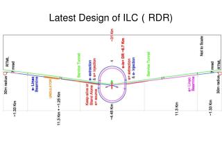
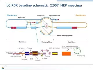
RDR Beam Delivery System ILC2006e (M. Woodley, A. Seryi et al) : Layout compatible for 1 TeV CM. http://www-project.slac.stanford.edu/ilc/acceldev/beamdelivery/rdr/ e- e+ Combined LW+pol +MPS Betatron Collimation Energy Collimation Energy Spectrometer Final Focus MPS Skew correction & emittance measurement Fast abort/Tuning line IP 2.2 km 2.2 km 0 500 1000 1500 2000 -2000 -1500 -1000 -500 0 S(m) One interaction region @crossing angle of 14 mrad with push-pull arrangements for two detectors. R. Versteegen’s talk on IR simulations (WG5).
RDR Beam Delivery System Concerns about combined functionality of MPS collimator, laser wire detector and upstream polarimeter measurements. It was planned to separate these functionalities for precise polarisation measurements. Possible shortening of 1 TeV CM BDS to allow more emittance growth due to synchrotron radiation. Push-pull requirement : location of QF1 unchanged. D1B adjusted according to L*. Different L* decks were prepared (A. Seryi) to study collimation depths and muons. Optics was not tuned for beam size and band width etc. L* D1B Recent attempt to address all these points alongwith required changes for SB2009.
SB2009 : Changes to BDS Design e-BDS Fast abort line Photon target + remote handling Undulator Dogleg Sacrificial collimators + chicane to detect off energy beams 400 m • Undulator based positron source moves to the end of the e- main Linac as part of central integration • Dogleg needs to provide 1.5m transverse offset at the target location at ~400m from the end of the undulator and ~40m drift near target area for remote handling. • Fast abort line in the beginning of the RDR BDS lattice before the undulator.
SB2009 e- BDS e-BDS Fast abort line Chicane to detect LW photons Polarimetry chicane Undulator Betatron collimation Dogleg Energy collimation Sacrificial collimators + chicane to detect off energy beams Final Focus Skew correction & emittance measurement DC Tuning line IP
The Dogleg Design • Theoretical Minimum Emittance (TME) lattice. • Provides 1.5m offset in ~400m • Emittance growth is ~3.8% (1TeV CM) • Decimation of dipoles is possible • The first and last dipoles in each of the two bending sections have lower bend angles to match the dispersion into, and out of, the dogleg. • These dipoles can be used to match and correct incoming errors to minimise the emittance growth seen in the dogleg sections.
The Dogleg Tolerances • Due to the space constraints and strong focusing in the dogleg design, the tolerances are tight. • The results of uncorrected mismatch entering the lattice, for a 10% emittance growth in the lattice at 1TeV CM (cf. 3.8% nominal). WEPE031, IPAC10
The Dogleg Tolerances • Important to understand the implications to tuning and tolerances due to the strong focussing dogleg lattice. • Preliminary studies indicate that very tight tolerances on the incoming dispersion, as well as the required trajectory correction. • Correction of these errors using the 4 “end” dipoles in the design has shown that it is possible to widen the tolerance levels significantly. • Additional correction for the trajectory within the dogleg needs to be looked at further and to understand if decimation of dipoles will be useful to relax the tolerances at 500 GeV CM.
Positron BDS Separated polarimetry chicane, combined functionality of laser wire and MPS still in the same chicane. Need laser wire simulations to see if this is okay. Polarimetry chicane LW photons+ MPS
Shortening of Energy Collimation and Final Focus Push-pull long 250 GeV 500 GeV • Emittance growth <1% @500 GeV beam for RDR. • First attempt to reduce the FFS length of push-pull deck by R. Versteegen (CEA). • Multiplied all the dipole lengths and drifts by 0.87 in the energy collimator and the FFS in order to approximately double emittance growth in these sections. • Re-tuned linear optics and sextupoles to optimise the luminosity and the bandwidth. 250 GeV 500 GeV Push-pull short
Shortening of Energy Collimation and Final Focus Reduced the total length by ~130 m and horizontal emittance increased to ~1.6%. long short Shifted vertically for illustration Short This length reduction is not yet implemented in SB2009. Long
Support for Travelling Focus in SB2009 A.Seryi, WE6PFP082, PAC09 • Create Travelling focus using a transverse deflecting cavity giving a z-x correlation in one of the FF sextupoles and thus provide z-correlated focusing. • The cavity will be located about 100m upstream of the final doublet, at the /2 betatron phase from the FD. • The strength required will be ~20% of the nominal crab cavity. • Such a cavity is not yet included in the lattice. • Tracking studies and possibly mitigation of higher order aberrations will be needed.
Possible Future Changes • On e- BDS side: • Needs re-designing of shorter fast abort line before the undulator. • Needs design of DC tuning line on electron side. Replace kickers with DC dipoles will affect the region between LW chicane and polarimetry chicane. • Details of power deposition in the tunnel and radiation effects will need to be evaluated. • Start-to-end simulations including the dogleg design. • Possible decimation of dogleg dipoles may be necessary if start-to-end simulations indicate. • on e+ BDS side: • LW simulations for combined functionality of LW photon detection and MPS for fast abort.
Possible Future Changes • On both BDSs: • Implementing shorter Final focus in final decks. • Support for travelling focus and low power beam dynamics simulations including collimation depth changes. • Study the possibility of merging full power tuning (tuning + fast abort on e+ side)dump with the main beam dump. SB2009 BDS Decks • No decks available publicly after RDR ILC2006e decks . The changes after the RDR need to be made available at some central place. • We will keep all these decks in present condition on EDMS soon with detailed comments for any future developments by interested colleagues.