ILC Beam Delivery System Layout and Lattice Design
200 likes | 340 Vues
This document presents insights and developments in the Beam Delivery System (BDS) layout and lattice design for the International Linear Collider (ILC). Key challenges such as head-on extraction, collimation performance, and crossing angle preferences are addressed. The contributions from the design and simulation team are highlighted, particularly the adaptation of the NLC’s design and the ongoing efforts to optimize the extraction line to reduce beam losses. The collaboration among institutions and the technical expertise in tuning methodologies for upcoming test facilities are also discussed.

ILC Beam Delivery System Layout and Lattice Design
E N D
Presentation Transcript
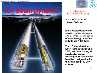
ILC Beam Delivery System Layout and Lattice Design Deepa Angal-Kalinin ASTeC, Cockcroft Institute Cockcroft Institute SAC 23-24th November 2006
Lattice Design and Simulation Team@CI ASTeC • Frank Jackson • James Jones • Stephan Tzenov • Deepa Angal-Kalinin Manchester • Rob Appleby • Dragan Toprek • Adina Toader Ph.D. Student • Anthony Scarfe CI SAC, 23-24 November 2006
Background • Before the technology decision for the linear collider (August 2004) – studies were mainly focussed on TESLA design • Problems related to head-on extraction • Poor collimation performance • Local chromaticity final focus system was designed but was not integrated with rest of the BDS • Alternative solutions to head-on : small vertical or small horizontal crossing angle – collaborations with LAL(Orsay), CEA(Saclay) • The team developed understanding of BDS design and requirements, implemented the required simulation codes in order to contribute to the evolving designs, established good collaborations After the technology decision • Small crossing angle solution and extraction line design required urgently • NLC collimation and final focus design was adapted to ILC, performance poor than NLC CI SAC, 23-24 November 2006
Interaction region - Crossing angle choice Very small 0 – 2 mrad Large 14 – 25 mrad Challenges in both the schemes • Large aperture shared magnets or compact magnets • No/ marginal/complete reliance on crab crossing • Axial/Non-axial field in the solenoid • Preserve pre-IP beam or emphasis post-IP beam • Reflected backgrounds or pre-IP constraints Physics prefers head-on with minimum background Incoming and outgoing beams Shared magnets => coupled design Separate magnets CI SAC, 23-24 November 2006
2mrad crossing angle extraction line design • CI team took a lead role in developing the 2 mrad extraction line design (part of SLAC-BNL-UK-France Task Force) • Due to higher cost of this line and challenges in magnet design, this crossing angle solution is now an alternative to the baseline with 14 mrad • CI team is working with LAL to optimise the extraction line to minimise the beam losses and magnet apertures • The optimised doublet (Appleby, Bambade, Toprek) at 500 GeV CM show significantly less losses in the IR region • Re-designing the rest of the line –minimum line to start with (Appleby) • Comparison of number of hits in VXD for the 2 mrad and 20 mrad (with DID) showed that the pair background increases for 20 mrad with DID => 14 mrad + anti-DID solution, now adapted for the RDR CI SAC, 23-24 November 2006
Contributions to the ILC : collimation optics • Tools to estimate the collimation depths for different crossing angle geometries • Better collimation efficiency Halo Tracking to FD entrance Original Performance Collimation depth Optimisations still continuing F. Jackson New Performance CI SAC, 23-24 November 2006
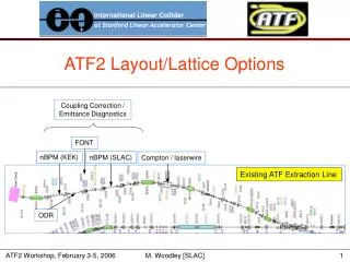
Contributions to the test facilities : ATF2 Beam sizes before and after tuning 1mrad QD0 Rotation • Tuning procedures and tolerances for the ATF2 • Several generic options for tuning of final-focus beam at IP – Traditional, Rotation Matrix, ‘dumb’ • Would like to test these algorithms at ATF2, which will present an ideal opportunity to provide some limited analysis of the viability of these methods. • Aim to increase our contributions with the help of Ph.D. student Anthony Scarfe • Expertise in tuning area, used to define the correction method in the long undulator section • The techniques developed are applicable to any accelerator Relative luminosity vs tuning knob J. Jones CI SAC, 23-24 November 2006
Contributions to the test facilities : ESA vert beam size 83m for collimator wakefield tests • Optics design for several experiments at ESA, SLAC (January’06 and April’06 beam tests) • Require small beam sizes in x and y planes for collimator wakefield and BPM experiments • Optics modelling challenges: high dispersion and SR in A-line • Careful emittance and Twiss measurements followed by beam tuning • Achieved goals of y100m and x~200m in separate lattice configurations horz beam size 240m for BPM studies F. Jackson CI SAC, 23-24 November 2006
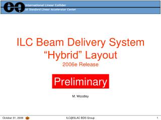
15 - 20 mrad gg 25 mrad 2 - 7 mrad gg 25 mrad ILC BDS Layout Changes First ILC Workshop, KEK, November 2004 Working hypothesis CI SAC, 23-24 November 2006
ILC BDS Layout Changes to Vancouver, July 2006 Snowmass, August 2005 CI SAC, 23-24 November 2006
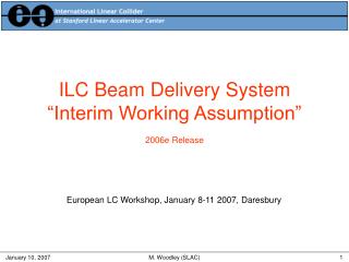
ILC BDS Layout Changes At Vancouver (July 2006), first cost estimates indicated significantly higher costs for 2 mrad line => base line configuration changed to 14/14 from 20/2. ILC GDE 14mrad 14mrad CI SAC, 23-24 November 2006
ILC BDS Layout Changes Valencia, November 2006 1 IR; two complementary push-pull detectors discussed with detector concepts and WWS ILC GDE 14 mrad CCR will be submitted this week by the BDS area leaders CI SAC, 23-24 November 2006
Present activities and Objectives • Contributing to several critical decisions on the ILC Interaction Region(s) • The BDS lattice design for the new baseline configuration • Risks vs performance • Push-pull task force • Optimisations and tuning studies • Layout details : CFS (shafts/caverns, IR halls) • Surface assembly for the detectors • Muon walls • Contributing to the RDR costing and writing • Optimisations for 2 mrad and modified head-on extraction line designs : cost effective, with input from magnet designers • studying the minimum layout design for these options without downstream diagnostics CI SAC, 23-24 November 2006
Future Plan : Beam Line Integration • Continue lattice optimisations for better performance, include realistic beam and machine errors • ATF2 skew/emittance LW, final focus, tuning, tail folding tests • Large crossing angle issues • Beam Line Integration :Major involvement of CCLRC’s engineering expertise • Lattice design and simulations • Collimation design • Vacuum design • Other CI major activities viz; crab system and beam dumps integrate naturally with this proposal Depends on the outcome of LC-ABD2 funding request Background & wake fields : main concern CI SAC, 23-24 November 2006
Future Plan : Collimation Design • BDS and extraction lines include ~20 different types of collimators • Most critical ones are with the adjustable gaps <mm and long tapers • CI is a leading contributor (with CCLRC, Birmingham and SLAC) on critical collimator issues: wakefields, survivability • ESA and simulations (C. Beard’s talk) • Future programme builds on this and will prototype ILC collimators for: • optimal mitigation of wakefields and component damage (and its detection); • overall engineering design: tolerances, alignment, movable jaws, cooling, machine protection. Depends on the outcome of LC-ABD2 funding request CI SAC, 23-24 November 2006
Future Plan : Vacuum Design • BDS has complex vacuum design : • Spoilers with fraction of millimetres openings to beam pipe radius of 200mm in the extraction lines • Synchrotron radiation at 250-500 GeV is significant • No experimental photon/electron desorption data exists at such energies • The interaction region geometry is most complex • Backgrounds in the detector are critical • Push-pull detectors will need special engineering solutions • Real vacuum chamber design (material and detailed designs) to estimate the wakes • Manufacturing and alignment tolerances - stringent • MPS issues Depends on the outcome of LC-ABD2 funding request CI SAC, 23-24 November 2006
ILC BDS : Collimation, crab system, beam dumps Layout & lattice design has a close link with the other tasks lead by the CI Collimation : Carl Beard Crab system : Peter McIntosh Beam dumps: Rob Appleby Next two talks ILC GDE CI SAC, 23-24 November 2006
The ILC beam dumps • ILC beam dumps and collimators are challenging - high power (18MW @1TeV CM) and short energy deposition showers • No experience with such beam dumps. Designs have been scaled from low power beam dumps • More simulation and prototypes required • Using CCLRC’s expertise in high power targets (ISIS, T2K), a programme lead by CI (Appleby) and CCLRC (Densham) has been initiated. • Definition of UK beam dumps programme, consisting of physics (CI) and engineering (CCLRC) • UK contribution to dumps and collimator costing • Physics simulation studies CI SAC, 23-24 November 2006
Future plans : Beam Dumps • The CI (Appleby) will lead physics simulation of dumps and collimators throughout the ILC • Energy depositions • Shielding and activation of water dump baseline and collimators • Costing and engineering expertise (CCLRC+CI) • Study of only viable alternative to main dump: the Noble gas dumps (Will seek new funding). Crucial if unknown show-stopper for water dump and alternative needed. • Site dependent Depends on the outcome of LC-ABD2 funding request CI SAC, 23-24 November 2006
Summary The CI team • has developed a skill base for optics and simulations • has made significant contributions to the ILC baseline and is contributing to the Reference Design Report • is very well integrated with the global design effort • intends to take a bigger role during the technical design phase with CCLRC’s engineering expertise Most of the proposed work depends upon the outcome of LC-ABD2 funding proposal submitted to PPARC CI SAC, 23-24 November 2006