Designing User Experience: Visual Specifications and Navigation Mapping
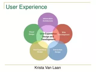
This chapter delves into the user experience (UX) model, focusing on both static and dynamic aspects of system interfaces. It highlights the importance of effective screen design, navigational paths, and the user interface elements involved in task execution. By utilizing user stories and use cases, designers can draft and refine UX models that capture user actions and environmental interactions. Key artifacts such as navigation maps and use case storyboards are discussed, illustrating how they represent the structure and flow of user interactions in web environments.

Designing User Experience: Visual Specifications and Navigation Mapping
E N D
Presentation Transcript
User experience model (Ux) • Visual specification of the user interface • Both static and dynamic aspects of the system • Covers user interface elements and their navigation • Main concern is how to present system data to the user • Not about attractiveness and visual appeal of the user interface • Capture how the user will be carrying out the task defined in the use case. • Use user stories and use cases to develop a draft of the user experience model. • This development may provide opportunity to refine use cases.
Ux: Elements • Screens: a list of screens makes up the user interface • Screens are related to each other with associations which identify navigation paths. • Navigation map: convey the structure of the user experience model • A screen may contain multiple input forms, each of which contains user input fields. • Screens and input forms have class stereotypes of <<screen>> and <<input form>>, respectively • The association between a screen and its forms is UML composition since forms are created and destroyedby the screen in the Web environment.
Screen and input form relationship Figure 4-2
Ux: Elements • Each screen should define the following: • The user actions that should be available to the user. User actions are modeled as class operations • The environment actions on the screen. Those actions are normally performed by the web browser or server on the screen. A “$” is used to prefixed the action name • One environment action for each message that can be displayed on the screen. Such messages may be like error message, notifications, system state • An attribute in the screen class representing the message type (e.g., “problem message”), its value depends on the error • One operation for each message to be displayed. E.g., $display invalid acct info message(). • Dynamic content of the screen, i.e., what the system has to display on screen. It covers business information. It is modeled as a set of attributes. E.g., display user account info, user name, address, etc are modeled as attributes.
Ux: Screen Mock-ups • Use screen mock-ups to model the user interface. • HTML documents may be created as mock-ups.
Create Account page Figure 4-9
Verify Account page Figure 4-10
Ux: Navigation map • It represents the navigation paths between screens. • It is a summary of the structure of the user interface • Identify each association with a name that represents the action that has initiated the navigation • Since a screen may contain multiple forms, a link should be from an input form to another screen, not from the parent screen to another screen. • You should be able to trace every navigation path to a flow of events in a use case. • Keep every screen within three navigational steps of the home screen • One map for each business use case package
Ux: Use case storyboards • They represent the dynamic aspect of the user experience model. • A storyboard for each use case. • Two diagrams: flow diagram and participants diagram • Flow diagram: • a sequence diagram representing the collaboration of the user and the screens involved for the task. • Messages in a flow diagram must match the operations defined in each corresponding class. • One flow diagram for each possible flow of events in the use case. • Participants diagram: • It contains the screens and input forms involved in the user interactions for the specific use case. • One participants diagram per storyboard.
Tracing storyboards to use cases. Figure 4-4
Participation Diagram: Create Acct Figure 4-7
Flow diagram: Basic flow of Create Account use case Figure 4-5
Participants diag.: Create acct Figure 4-6
Flow diagram: Create Acct Figure 4-8
Ux: Navigation map • It represents the navigation paths between screens. • It is a summary of the structure of the user interface • Identify each association with a name that represents the action that has initiated the navigation • Since a screen may contain multiple forms, a link should be from an input form to another screen, not from the parent screen to another screen. • You should be able to trace every navigation path to a flow of events in a use case. • Keep every screen within three navigational steps of the home screen • One map for each business use case package
User Acct Mngt - navigation map Figure 4-3
Ux: Summary • Elements: screens and input forms • Artifacts: • Navigation maps (static): valid navigation paths between screens and input forms • Use case storyboards (dynamic): the realization of the flow of events for the uses that involves graphical user interactions • Storyboards: • Flow diagram: the sequence of screens navigation for a specific task • Participants diagram: the screens and input forms and the navigation paths for a specific task • One navigation map per package • One use case storyboard per use case • Each storyboard should contain at least one flow diagram for the basic flow of the use case. • Each storyboard must be traceable to a use case