Download
1 / 23
230 likes | 460 Vues
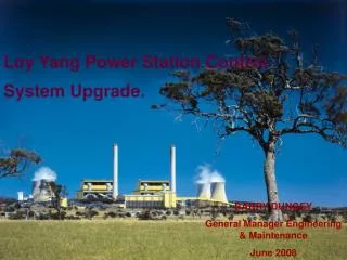
Loy Yang Power Station Control System Upgrade. BARRY DUNGEY General Manager Engineering & Maintenance June 2008. Key Project Objectives:. Original control system is of mid 1970’s design with circuit board, relay and wire wrap technology.

E N D
Loy Yang Power Station Control System Upgrade. BARRY DUNGEY General Manager Engineering & Maintenance June 2008
Key Project Objectives: • Original control system is of mid 1970’s design with circuit board, relay and wire wrap technology. • The main driver for the project is the difficulty in supporting obsolete control equipment.( Our policy is to run for approx 5 years following withdrawal of support by our equipment supplier) • The opportunity is also being taken to gain improvements in system performance and reduce business risk exposure. • ( i.e. Alternative control room) • Plant trip rates were increasing with a significant number due to control system faults. • Upgrade will include the installation of a separate plant safety system. • Complete unit cut over to be achieved in 35-40 day outage duration
Loy Yang Power Expectations • The current control system is fairly tight as it is already being run on a digital platform, hence LYP are not expecting significant direct improvements in efficiency as a result. (Some studies indicate that up to 2% improvement is possible from older systems) • The system will deliver flexibility to do things smarter, fault find easier, and implement future plant logic change easier. • The supplier has provided a guarantee that they will support the new control system for 35 years, hence no further significant upgrades are expected in the remaining life of the plant.
Yokogawa Site Observations • Site surveys noted that the current control strategies are sound. • Boiler thermocouple dynamic response suitably fast to allow for quick movement in loads. • Existing spray valves and actuators not significantly limiting performance • Existing controls have some issues when limits are reached – wind-up, excess output pull-back, etc
Benefits from Yokogawa control design • Integration between steam temperature and combustion controls minimises interaction • “Over-firing” minimised by using transient contribution of superheater sprays to main steam pressure control • Contributes to wider operating range from milling plant • Boiler thermal stress reduced • Flexibility on turbine ramp rates possible • On line efficiency tools improved.
Benefits (Continued) In summary, the current process is about achieving incremental improvements, particularly with: • Start up and shutdown sequences • Better trim controls associated with excess air (oxygen). • Maximising future flexibility with an open system which can accept third party products. • Improved Operator information and diagnostics
Optimised Sootblowing • Loy Yang Power has four superheater elements, 2 reheater elements and an economiser within each furnace convection path. • To manage boiler fouling, 74 sootblowers are used to clean the elements using high pressure steam from the Reheat Steam System. • The original design used a time based operation system with two cleaning cycles per day.
Optimised Sootblowing - NGISB • An optimised sootblowing system (NGISB - Next Generation Intelligent Sootblowing System) has been installed on one unit as a trial. It uses a Synengco supplied NGISB system interfaced to PLC based sootblower controls supplied by Siemens. • The NGISB gathers data from the plant historian at near real time and continuously calculates the ideal sootblower schedule using a thermal boiler model within business rule constraints.
Sootblower Optimisation System Aims • Reduce sootblowing frequency • Maintain boiler attemporator spray flows within the ideal valve control range • Minimise Reheat Spray Flow • Maintain Steam and Metal Temperatures close to target and minimise alarm conditions to maximise thermal efficiency. • “Set and Forget” operation.
Optimised Sootblowing Results • Sootblowing frequency reduced to 32.5% of the original time based schedule. • Annualised Savings per Unit • 24.7 TJ of energy • 8.1 Ml of Cold Reheat Steam • 4,900 Tonnes of CO2
Optimised Sootblowing Results (Continued) • Reducing RH Spray Flow to a minimum has a positive impact on overall steam cycle efficiency – estimated to be 0.3% • Reduced thermal excursions in the boiler due to sootblowing leading to a more stable boiler. • Better than 12 month payback on current costs.