Download
1 / 57
600 likes | 969 Vues
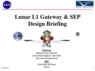
Lunar L1 Gateway & SEP Design Briefing. Gateway Element Lead: Frank Lin Lead Systems Engineer: Jim Geffre JSC Gateway Design Team SEP NASA GRC SEP Team 11/2/01. Briefing Objectives. Review work done to date by JSC Advanced Design Team on Gateway architecture

E N D
Lunar L1 Gateway & SEP Design Briefing Gateway Element Lead: Frank Lin Lead Systems Engineer: Jim Geffre JSC Gateway Design Team SEP NASA GRC SEP Team 11/2/01
Briefing Objectives • Review work done to date by JSC Advanced Design Team on Gateway architecture • Focus on design of Gateway Element • Review work done to date by NASA GRC on Gateway architecture • Focus on design of Solar Electric Propulsion (SEP) system
Briefing Outline • Gateway Architecture Overview • Gateway Mission Overview • Requirement Development • Mission Requirements and Constraints • Functional Allocation Matrix (FAM), N2 Charts, Sub-system Requirements • Gateway Sub-Systems Descriptions • Preliminary Hazard and Reliability Analysis • Future Technology Investments • Open Issues/Forward Work • Solar Electric Propulsion
Gateway Architecture “Earth’s Neighborhood” GPS Constellation Crew departs from and returns to ISS L1 Gateway Lunar Habitat Lunar Lander Crew Transfer Vehicle • L1 Gateway • “Gateway” to the Lunar surface • Outpost for staging missions to Moon, Mars and telescope construction • Crew safe haven • Lunar Lander • Transports crew between Gateway and Lunar Surface • 9 day mission (3 days on Lunar surface) • Lunar Habitat • 30-day surface habitat placed at Lunar South Pole • Enables extended-duration surface exploration and ops studies • Crew Transfer Vehicle • Transports crew between ISS and Gateway • Nominal aerocapture to ISS, or direct Earth return contingency capability
Gateway Mission Profile Launch Gateway on DELTA IV-H Activate Critical Systems, Inflate & Checkout Gateway LEO Operations Launch Shuttle with Gateway Outfitting Crew Shuttle Rendezvous and Docking with Gateway Outfit & Checkout Gateway SEP Autonomously Dock with Gateway Launch SEP on DELTA IV-H Autonomously Deploy SEP Solar Arrays Gateway and SEP spiral to LL1 (unmanned) Up to 15 days* Lunar Surface Mission Crew Arrives at Gateway in CTV Crew Returns to Earth in CTV 30 days LL1 Operations Telescope Mission Deliver Lunar Lander to Gateway (unmanned) 30 days Gateway Logistics Resupply / Cargo Delivery (unmanned) Science Mission *Reflects crew time spent in Gateway
Go/No go for TLI? Repair successful? Gateway go/no go for SEP launch? TLI? Dock successful? Stack go for TLI ? Gateway Mission Flow Chart Send replacement/repair mission on Shuttle Launched on Delta IV Stable on-orbit config Inflate, activate, and checkout in LEO All systems go? Y N N Y All systems go? Shuttle outfitting in LEO, final Checkout (detailed list TBD) Done N N N Y Y Y SEP Rndz/ dock with Gateway at LEO Fully deploy SEP arrays Partial SEP array deploy Launch SEP stage Shuttle returns Y Y N Attempt repair on later Shuttle mission if possible N Stabilize Gateway and SEP N Y Lunar lander Lunar mission * Gateway uses chem prop system for separation and L1 insertion Config Gateway for stable L1 ops CTV Transit from LEO to LL1 SEP stage undocks for return Telescope arrives Telescope mission CTV * Refer to Lunar L1 Architecture Operational Events Flow Chart
Requirements and Constraints Top Level Requirements • Stage telescope construction and lunar surface missions from Gateway • Two telescope construction missions per year • Two lunar surface excursions per year • Support crew of four • Design lifetime of 15 years • Simultaneously support three docked vehicles (CTV, Lunar Lander, Logistics Module) • Provide EVA capability for nominal operations • Maintain position at lunar L1 Lagrange point • Autonomous transfer from low-Earth orbit to lunar L1 Design Goals and Constraints • Incorporate inflatable technology • Delivery to lunar L1 via solar electric propulsion • Crew safety is highest priority • Maximum system technology demonstration capability • Maximize use of technologies viable for future human space exploration
Gateway Requirement Development Process FAM N2 Chart • Defines System interface connectivity for Gateway by mission phase • Defines type and disposition of system interfaces • Defines Gateway functions for each mission phase • Identifies Gateway Sub-systems for each mission phase Sub-system Requirements • Defines required systems for each mission phase
Gateway Element Summary Inflatable Airlock (4) Radiators (3) • Element Design Lifetime: 15 yrs • Element Mass: • Launch: 22,827 kg • Outfitting: 588 kg • Post-outfitting: 23,415 kg • Resupply mass/Volume: • 6-months: 805 kg / 3.878 m3 • 24-months: 2,824 kg / 7.587 m3 • Element Volume: • Launch: 145 m3 • Operational: 275 m3 • Power provided: • PV Array: 12 kW Nom/14.4 kW Peak • Energy Storage: • Batteries 71 kW-h • Flywheel 20 kW-h • Support Missions: • Outfitting at LEO: One mission/architecture • HF&H consumables: Two missions/year • ECLSS/Prop: One mission/two years • Estimate Element Cost: XX M • System Reliability: 72% ACS Cupola RCS jets Prop & ECLS tanks EVA Work Platform/ Telescope Assembly Site P/V Arrays (2) RMS
Gateway Configurations Launch Configuration LEO, Transit, L1 Stand-by Configuration Lunar Operations Configuration Telescope Operations Configuration
Gateway Systems • Attitude Control System (ACS) • Avionics • ECLSS • EVA • Human Factors & Habitability (HF&H) • Power • Propulsion • Robotics • Structures • Thermal Control • Mission Operations • Mission Success
Attitude Control System Design Summary • System Requirements: • Maintain Solar Inertial Attitude for Gateway in low-Earth orbit and at Lunar L1 • Provide 1,000 N-m-s of Momentum Storage • Provide 20,000 W-hr of Energy Storage • Assumptions Made: • Momentum storage requirements are equivalent to NGST • Flywheel system axis must be aligned with one of the Gateway’s body axes • Concept Trades Considered: • Flywheels • Control Moment Gyros • Chemical RCS • Selected Technologies: • Integrated Power and Attitude Control System (IPACS) Flywheels • Rationale: The flywheel system offers the potential for a coupled energy storage and attitude control capability, and is the least mass alternative. A CMG system would require a larger lithium-ion battery system to accommodate the extra 20 kW-hr of energy storage. Chemical RCS requires a large propellant load to handle the attitude control needs for 15 years.
Attitude Control System Design Summary System Specification: • Physical dimensions: Mass: 318 kg Volume: 0.288 m3 • Provide 70 kWe peak power to user • TRL 3 Issues and Concerns • None Forward Work • Determine flywheel system reliability & lifetime IPACS Flywheel System
Avionics System Design Summary • System Requirement • Provide guidance, navigation, control, communications, and health monitoring of Gateway • Assumptions Made • Communications would follow proposed Ka-band upgrade and operate in the 32ghz range • UHF would be used for space-to-space communication between vehicles • Flight Computer System would be a quad-redundant system based on the X-38 Fault • Tolerant Processor model • The flight computer, itself, would be based on the Universal Mini-Controller (UMC) • Flight Computers would be distributed so that they could also collect data from subsystems • near their respective locations • Wiring would include a combination of fiber optics, wireless, and parasitic use of the power • buses where applicable, optimally selected to minimize mass and maximize reliability • Concept Trades Considered • NA
Avionics System Design Summary • System Specification • Mass is 251kg • Total Volume Required: 1.0 m3 • Overall Sub-system TRL Level: 6 • Issues and Concerns • None • Forward Work • None
PAU Stellar Attitude Sensor PAU Diplexer PAU Low Noise Amplifier PAU INS PAU Transponder Flight Computer with Data Acquisition & Control Avionics System Design Summary Ka-band Antennae Gateway Avionics Architecture Omni Antenna Switch Antenna Switch Video PAU Video System Displays Digital Voice SSVR (UHF) Ka-Band Data Buses Power Amplifier Power Amplifier LDR Flight computers INS Crew Interface - Hand Controllers - Switches HDR Intercomputer Bus Sensor Data HDR and LDR Data
ECLSS System Design Summary • System Requirement • Control cabin temperature, humidity (NASA-STD-3000), and pressure (select at 9 psia) • Provide crew consumables (O2, N2, H2O) for cabin, airlock and EVA • Provide closed air, water recovery and waste management systems to minimize re-supply • Assumptions Made • Two-year re-supply period • Crew daily O2 consumption rate - 0.84 kg/person/day • Crew drinking and food preparation – 2.8 kg/person/day, hygiene, 6.8 kg/person/day • No dishwasher, no laundry, no salad machine • Concept Trades Considered • High pressure vs. cryogenic N2 and O2 storage • CO2 removal technology: 4 x BMS vs. solid amine • Biological water recovery technology (BWR) vs. Vapor Phase Catalytic Ammonia Removal technology (VPCAR) • Selected Technologies • Cryogenic w/ High pressure for Rationale: Cryogenic system has less mass. High inflation pressure tanks for initial Gateway inflation for shorter inflation time. • 4 x BMS CO2 removal system Rationale: relative mature close CO2 removal system • VPCAR Rationale: Mass, volume and power benefits. Shorter • turn-around time. Restart ability.
ECLSS System Design Summary • System Specification • ECLSS System Mass: 2851 kg • Dry Mass: 2174 kg • Fluid Mass: 677 kg • ECLSS System Volume: 15.9 m3 • TRL Level: • CO2 removal 9 • Oxygen generation system 6 • CO2 reduction system 6 • CO2 compressor 3 • Trace contaminant control 4 • Issues and Concerns • NASA-STD-3000 set long-term mission spacecraft pressure at 14.5 – 14.9 psia. • Forward Work • Report • Fire detection and suppression 9 • Vapor Phase Catalytic Ammonia Removal (VPCAR) 4 • Water recovery from brines (air evaporation system) 6 • WRS product water post processor (ion-exchange beds) 6 • Solid Waste Processing (Lyophlilization water recovery) 3
Post Air Evaporation processor System (AES) ECLSS System Design Summary ECLSS Water RecoverySystem Block Diagram Respiration, condensate Potable Water Tank Urine + flush water VPCAR Hygiene wastewater Food preparation 45 kg/day brine vacuum Cond HX vent air Sabatier CO2 reduction subsystem CH4,CO2,H2 ECLSS Air Revitalization System Block Diagram 4BMS CO2 TCCS H2O H2 O2 O2 Gen. subsystem Waste Processing System Cabin at 9.0 psia O2 30% N2 70% Air leaks O2 Tank N2 Tank O2 from propulsion cryogenic storage Water from water recovery system High Pressure
EVA System Design Summary • System Requirement • Store 4 Space Suits from CTV • Support Four six month mission phases prior to resupply • 10 EVAs (8 hr) for Telescope mission for four missions • Gateway maintenance at one EVA per six month mission • Total of 84 4 hr EVAs prior to resupply • Assumptions Made • 10 EVAs for Telescope mission • 1 EVA for Gateway maintenance per six month mission • Two tool boxes for Telescope assembly • Concept Trades Considered • Recharge system to recharge 3000 psi PLSS Oxygen tanks from low pressure cryo tanks • Chose thermal compression to 850 psi, mechanical compression from 850 psi to 3000 psi, (ORCA), ECLSS emergency repress tank used as accumulator for rapid refill then recharged using compressor. • System Specification Dry Mass Volume Minimum TRL • Space Suits 636 kg 3.62 m3 TRL 2 • Vehicle Support for EVA 212 kg 0.34 m3 TRL 3 • EVA Translation Aids 123 kg 3.36 m3 TRL 9 • EVA Tools 132 kg 0.2 m3 TRL 9 • Airlock 433 kg 8.18 m3 TRL 3
Transvector Trim cooler Purge Valve Fan Swing Bed CO2 & Humidity Remover Accumulator Battery Comfort Heater Pump C & W Radiator H2O Evaporator Lunar Space Suit Schematics EVA System Design Summary Issues and Concerns • Lack of Technology Development Funds to raise low TRL items within schedule needs Forward Work • Light weight PLSS • Recharge system to recharge 3000 psi PLSS tanks from 150 psi lox supply
ECLSS High Pressure O2 Storage PLSS Tank Oxygen Compressor 800 to 3000 psi 850 psi Relief Valve Flexible Umbilical Cryo Coolers Q = 90 BTU/lb LOX at sub critical pressures ECLSS use Gateway Space Suit Oxygen Recharger Schematic ECLSS top off configuration Gateway EVA System Block Diagram
Habitability and Human Factors (HF&H) System Design Summary • System Requirement • Provide consumables for 60 days • Provide a minimum habitable volume of 60 m3 (15 m3/person) • Comply with MSIS/NASA-STD-3000 • Assumptions Made • Maximum contingency duration of Gateway use is 60 days, with a 25-day crewed maximum nominal mission phase. • Gateway station provides an “oasis” in terms of living environment • Concept Trades Considered • Crew Quarters: Dorm Style v. Private Quarters • Waste Collection Facility: Plumbed v. self-contained facility v. bags only • Hygiene Facility: Partial-body cleansing v. Full-body cleansing • Medical Equipment: Med kit only v. nominal mission life support v. contingency scenario life support • Exercise Capability: No exercise v. limited resistive v. cardio only v. resistive and cardio training • Food System: Shuttle food system (pure-ambient) v. Conditioned food • Clothing: Clothing as consumable v. washer/dryer • Acoustics: Acoustic abatement throughout module v. Acoustic abatement at CQ and equipment room hatch only
Habitability and Human Factors (HF&H) System Design Summary • System Specification • Mass: 2507.48 kg • Volume: • HF&H equipment: 15.04 m3 • Habitable volume: 200 m3 • TRL Level: 8 • Issues and Concerns • Conditioned food: This is a nutritional need for the health of the crew, but is currently not considered feasible because of infrequent resupply missions to the Gateway/radiation issues • Windows: Additional viewing windows (for scientific observation and recreation) are preferable in the Gateway • Resupply: Logistics of resupply of crew-preference and crew-specific items (e.g. clothing, food, hygiene consumables) needs to be more well-defined with consideration for radiation exposure • Forward Work • Research possible HW mass losses between now (current Station hardware) and fly date • Double check depressurization compatibility of HW and supplies • Continue modifying detailed layout • Research exercise technologies • Research food technologies • Investigate lighting effects and simulated windows
Habitability and Human Factors (HF&H) Cabin Layout SMF HDTV Stowage Exercise Facility CQ CQ Galley HF Workstations CQ WCF CQ CQ = Crew Quarters HF = Hygiene Facility WCF = Waste Collection Facility SMF = Space Medical Facility HDTV = High Definition TV Stowage
EPS System Design Summary • System Requirements • Provide 1kW (Peak) during ascent, orbit injection and deployment for Gateway survival and initial on-board operations. • Provide 2KW during LEO operations (90 min. orbit with 45 min. eclipse time) prior to rendezvous with SEP. • Provide continuous 12 KW while at LL1 with an energy storage capability to compensate during the 13 hr maximum eclipse time every 6 weeks for the entire Gateway life cycle of 15 years. • Assumptions Made: • Power generation and storage sized to include 30% contingency and 20% additional mass for secondary support structure. • It assumed that the overall EPS system is about 70% efficient (user power/power generated) • Arrays 1 fault tolerant, but rest of H/W 2 fault tolerant (ring bus architecture assumed). • High voltage DC to be provided by array and batteries and distributed within the Primary Distribution System. • Secondary Distribution System is 115 Vac, 3Ø, 400 Hz • Two Tertiary Distribution Systems included: 28 Vdc and 110Vac, 1Ø, 60Hz.
EPS System Design Summary Concept Trades Considered: • Ultraflex vs. Inflatable PV Array • Thin-film vs. Fiber Li-Ion Battery • 28 Vdc vs. 115 Vac, 3Ø, 400Hz Selected Technologies: • Ultraflex, Fiber Li-Ion integrated into structure, 115AC, 3Ø, 400Hz Rationale: Lower mass and design simplicity System Specification: • Physical dimensions: Mass: 1,335 kg Volume: 27 m3 • Provide 12 kW nominal with 14.4 kW Peak to user • Arrays capable of 20.7 kWe • TRL • PV Arrays 7 • Deployment Truss 6 • Battery 2 • Wiring Harness 9 • PMAD 6 Issues and Concerns • Development of 400 Hz RPC Box • Development of Fiber Li-Ion Battery System Forward Work • Full assessment of the Fiber Li-Ion battery capability and integration into vehicle structure.
EPS System Architecture Charge / Discharge Unit #1 Fiber Li-Ion Fabric Section Charge / Discharge Unit #1 Representation of a Single String of the “Inner Loop” Power Distribution System Fiber Li-Ion Fabric Section UltraFlex Array Unit #1 UltraFlex Array Unit #2 Bus B Bus C Bus A Relays 155 Vdc RPC Box INVERTER Inverter Inverter Inverter RPC Box RPC Box 115 Vac, 3Ø, 400 Hz INVERTER INVERTER Secondary Distribution System RPC RPC RPC Relays Fiber Li-Ion Fabric Section Fiber Li-Ion Fabric Section Charge / Discharge Unit #2 Charge / Discharge Unit #3 Power Bus #3 Power Bus #2 Tertiary Distribution System Power Bus #1 Charge / Discharge Unit #2 Charge / Discharge Unit #3 110 Vac, 1Ø, 400 to 60 Hz Frequency Converter 115 Vac, 3Ø, 400 Hz to 28 Vdc Converter EPS System Block Diagram Primary Distribution System
Propulsion System Design Summary • System Requirement: • Provide Gateway vehicle with approx. 50 m/s delta V per year for station keeping • Assumptions Made: • Propellant resupplied once every two years • Vehicle lifetime 15 years • Propulsion system for station keeping only, no ACS • Book-keep ECLSS and EVA O2 (491 kg) • Concept Trades Considered: • Propellant selection -Tridyne, Hydrazine, NTO/MMH, LOx/CH4 • System size vs. regularity of resupply • Concept(s) Selected: • 12 x 110 N LOx/CH4 engines Rationale: Mass/volume savings, non corrosive exhaust products • System Specification: • Mass: 176 (dry) kg. 1,444 (total) kg. • Dimensions/Volume: Approx. 1.23 m3 tank
Propulsion Preliminary Design Summary • Issues and Concerns: • Thruster placement due to the nature of the inflatable structure design and plume impingement on solar arrays • TRL: • Engines 4 • Cryocoolers 4 • Forward Work: • None
Propulsion Preliminary Design Summary Integrated LO2/LCH4 Gateway Propulsion Schematic 110 N RCS Engines 322 s Isp 3.8 MR TVS
Robotics System Design Summary • System Requirement • Support EVA activities and maintenance, inspection and mobility of both intra- and extra- vehicular systems • Assumptions Made • Large arm needed for gross payload manipulation • Dexterous robot needed for human-equivalent manipulation • Will use automated “smart systems” where appropriate • Concept Trades Considered • No tasks or requirements were identified that required a trade study • System Specification • Robotic Manipulator System • Mass: 543 kg • Dimensions/Volume: Arm- 15.2 m x Æ.33 m • RWS Stowed- ISPR 1.01 m x 1.07 m x 1.98 m • TRL Level: Arm- 9 • RWS- 8 • Robonaut • Mass: 136 kg • Dimensions/Volume: .71 m³ • TRL Level: 5
Robotics System Design Summary • Issues and Concerns • Current work reflects generic robotic requirements defined as: • Gross payload manipulation • Human-equivalent manipulation • Forward Work • Continue development of Robonaut to increase autonomy and functionality • Define and identify the robotic requirements associated with telescope construction • Size RMS based on telescope construction requirements
Robotics System Design Summary Available Solutions
Structures System Design Summary • Structural Requirements • Interface to Delta IV Heavy • Support crew of 4 for 25 days • Provide docking mechanisms for CTV and Lunar Lander • Provide worksites for constructing/assembling telescope • Provide structure to mount other systems within primary structure • Assumptions Made • 6 g axial and 2.5 g radial launch loads • 9 psi nominal internal pressure • Concept Trades Considered • Hardshell vs. Inflatable vs. Hybrid Gateway Structure • Hybrid structure encouraged by architecture team for future applicability to future exploration missions • System Specification • Gateway total Mass: 7354 kg • Overall length: 9.3 m • Hard shell Dia.: 4 m • Inflatable Dia: 9 m
Structures System Design Summary • Issues and Concerns • Radiation protection not incorporated into design due to unavailable design support from SF2 • Material properties for the mission at L1 are assumed to be acceptable at EOL for the mission duration. • Procedure for replacing MM/OD shielding on inflatable not identified • Forward Work • Incorporating radiation protection • More detailed design and analysis of primary structure
TCS System Design Summary • System Requirement • Collect, Transport, and Reject 15.6 kW to space • Provide heaters to maintain low temperature limits of the Gateway shell • Assumptions Made • Radiators are freeze tolerant • All radiator panels see deep space environment • Air distribution over the internal inflatable wall prevents condensation (no heaters on fabric) • Concept Trades Considered • Single Loop vs. Dual Loops • TCS working fluid types • Flow Through Radiators vs. Heat Pipe Radiators • Number of Radiator panels • Concepts Selected • Single loop Rationale: Less hardware, no toxic fluid needed • 60% propylene glycol/40 % water Rationale: Freeze tolerance, safer working fluid • Flow through radiators Rationale: Lower mass • Three radiator panels Rationale: Redundancy
TCS System Design Summary • System Specification • 663 kg Total Mass • 115.4 kg Fluid mass, 547.6 kg Dry mass • 3.39 m3 Total Volume • 0.84 m3 ETCS & Radiators, 2.56 m3 Multi-layer Insulation • TRL levels • Flow through, flexible, freeze tolerant radiators: 4-5 • All other TCS components: 9 • Issues and Concerns • Working fluid concerns regarding freeze tolerance • Will single loop architecture function in the environment • Inflatable inner wall air flow • Exposure of equipment in inflatable section to space vacuum • Equipment operation at 9.0 psia operating pressure • Forward Work • More detailed analysis to characterize the thermal environment • Evaluate test data for flexible radiators and heat pipes • Investigate attachment methods for flexible radiator to inflatable shell
Gateway Thermal Control System Schematic Flexible Radiator Radiator bypass External Coldplates Internal Coldplates Condensing HX TCS System Block Diagram Redundant Pumps
Mission Operations Assessment • Gateway checkout in LEO • Critical Gateway systems to be checked out prior to Shuttle outfitting mission • Pressure vessel integrity • Life support system • Electrical power system • GNC/attitude control system • Data processing • Communication system • Thermal control system • Remaining systems will be checked out during Shuttle outfitting mission and prior to transfer to Lunar L1 • Robotics • Waste collection system • HF&H • Inflatable airlocks • LEO Outfitting Mission • Pressurized cargo carriers considered: • MPLM, SpaceHab module • Recommendation • Modify double SpaceHab with IBDM • Zero Shuttle modification required • Launch Gateway SRMS on sill longeron and relocated using SRMS
Mission Operations Assessment • Gateway Resupply strategy • Immediate resupply • CTV to carry immediate crew resupply items • Limited volume and mass items • CTV to leave contingency food on Gateway • CTV to swap out shelf life sensitive items that are common on CTV and Gateway • Medical supplies, food, etc. • Short term resupply • Once every six months • Use Lunar Lander habitable volume for stowing resupply items • Resupply items include: Food, clothing, medical supplies (items that are less time and radiation sensitive), misc. crew supplies, etc. • Long term resupply • Once every two years • Require a module capable of carrying pressurized and unpressurized cargo • Identified as a new element to the Gateway architecture. • Resupply items include: Station keeping propellant, ECLSS system consumables, large ORUs and tools, experiments, etc.
Safety and Mission Assurance Strategies for HumanExploration – Gateway II PHA Summary • Open Work from Hazard Analysis • An analysis of the radiation protection of the vehicle's final configuration should be done. This will affect the hazard controls for two conditions identified concerning excessive radiation in the crew habitable environment.
Conclusions • System Reliability & Sparing • Reliability Block Diagram Analysis predicted a Gateway reliability with no repair of approximately 72%. This reliability is associated with mission success modeling of all the supporting subsystems which includes EVA suits for telescope construction. • Sparing requirements for one re-supply cycle (10,225 hours) of the Gateway will be significant given the reliabilities of the modeled subsystems. • Crew Safety • The PHA has documented the subsystem design mitigations controlling the hazards identified. • All subsystems will meet fail-op/fail-safe requirements as specified in the Human Ratings Requirements with the option of the LTV ticket back to LEO. This however only applies to crew safety and not mission success. • Open Work: Analysis to evaluate the inherent radiation protection of the Gateway design
Gateway Mass Summary Mass Limit: 35,400 kg (Delta IV Heavy Capability)
All masses and volumes are entered in metric units Cost estimates are shown in 2001 dollars Cost includes hardware development and manufacturing Assume three prototype for each system 2 prototype / flight unit Year of technology (YRTECH)value is 2005 Development start date(DSTART)=1/02 Completion date of first prototype (DFPRO)=4/07 Completion date of last proto/flight unit (DLPRO)=4/09 Twenty percent program reserve added to PRICE-H cost figures Does not include recurring or operations costs Gateway Cost Summary Gateway $ 979.1 M STR & MECH $ 453.8 M ACS $ 31.3 Avionics $ 50.8 EVA $ 5.1 Power $ 59.1 M Propulsion $ 87.9 M To Be Updated Systems Integration & Test $ 59.2 M Thermal Control $ 62.2 M Human Factors & Habitability $ 0.45 M ECLSS $ 130.2 M Robotics $ 104 M PRICE –H Cost Analysis Assumptions
Future Technology Investments • ACS • Flywheel technology • ECLSS • Vapor Phase Catalytic Ammonia Removal (VPCAR) • Lyophilization Water Recovery • EVA • Inflatable Airlock • Next Generation Space Suit • EPS • Fiber Li-Ion Batteries • Propulsion • Cryo Cooler • Structures • Radiation Protection Materials and Methods • MMOD Protection Materials and Methods