06411 Micro Nucleating Bubble Engine
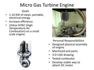
This project aims to design a millimeter-sized piston-like engine that uses bubble nucleation to produce mechanical oscillations. The goal is to create a proof-of-concept engine that can be portable, lightweight, and easily replaceable. The engine will be powered by a control system to regulate bubble growth, and its operational specifications will be benchmarked for efficiency and operation time.


06411 Micro Nucleating Bubble Engine
E N D
Presentation Transcript
06411 Micro Nucleating Bubble Engine Team Members Steven Nathenson Joseph Pawelski Joaquin Pelaez Andrew Pionessa Brian Thomson Project Sponsors Dr. Crassidis Dr. Kandlikar Project Coordinator Dr. Walter
Introduction / Project Goals • Millimeter scale • Piston like design • Performance comparison • Small budget • Control bubble production • Mobile • TO GRADUATE
Major / Critical Specifications • Customer Requirements / Objectives • Be portable and lightweight • Work on principles of bubble nucleation to produce mechanical oscillations of a piston • Determine appropriate fluid for ideal bubble behavior • Utilize a power supply or a battery in conjunction with a control system to regulate heater and control bubble growth • Utilize a miniature heating element • May need to be protected so it does not break or fracture • Must be easily replaced • Stay within the budget • Create a millimeter-sized engine • Create a proof-of-concept • Theoretically prove engine design • Create and test a working engine • Benchmark operational specifications, such as operational frequency, efficiency, and operation time • Runtime • Must run for about 20 seconds • The liquid reservoir might need be cooled via a heat exchanger to allow for longer runtimes • Reduce friction between piston and casing
Major / Critical Specifications (cont.) • Functional Requirements • Contained within (1 ft3) volume • Piston size of 5-10 mm • Must function at around 5-10 Hz • Design Specifications to Date • Pyrex Cylinder • ID: 0.218” • OD: .0375” • Operating Temp: -20°F to +446°F • Teflon Piston • Platinum wire heating element • OD: 0.002” • Resistivity: 10.6 x10⁻⁸ W·m • Length: 1-2 mm • Base plate with two aluminum electrodes
Feasibility / Technical Concerns • Piston design – most feasible • Easy to manufacture • Simple • Easy to test • Smallest time of development • Preferred design of sponsor • Risk assessment contained within Pre-Read Package • QFD Analysis yields concerns • Bubble control • Piston displacement • Piston size • Power input • Accurate theoretical models* *Not contained within QFD analysis
Heater • During the brainstorming portion of the project, there were several heater ideas proposed. The initial concepts were: • Straight wire • Square wire • Circular wire • Concentric wire • Metal plate • Additionally, there were several implementation methods proposed for this heating element. They are as follows: • Resistant wire • Protective plate • Other method…
Navier-Stokes Model • Assumptions • Steady State • One dimensional flow • Fully developed flow • Pressure drop is constant • Constant properties • Laminar • Resulting equation
Systems Model (cont.) Find damper constantB2 • Damper constant B2 represents the shear between the piston and cylinder created by the change in velocity between the piston and water column. • Shear velocity must be adjusted because of the change in area between the cylinder diameter and the piston based on the conservation of mass equation. Find spring constantK1 Spring constant is derived from the buoyancy force enacted by water on the piston. • Assumptions: • Shear forces due to air are negligible • Shear forces within rising water column are negligible * • Shear between the piston and cylinder is calculated assuming shear between infinite parallel plates. • Velocity distributions and vortices created by bubble propagation are negligible, for systems control volume flow is assumed laminar. • *Flow in the cylinder is not fully developed.
Matlab Simulation %Laminar flow check disp(' ') disp('Is the flow in the fluid bath laminar or turbulent?') disp(' ') for i=1:2001 if(Re(i)>2300) disp('The flow is turbulent') lamturb(i)=0; break else lamturb(i)=1; end end if(all(lamturb)==1) disp('The flow is laminar') end • User input parameters • Automatic assumption checks • Current bubble growth function: Mikic et. al. (1970) • Future bubble growth function: Experimentation of our specific conditions Is the flow in the fluid bath laminar or turbulent? The flow is turbulent
Control System Concepts Control System Concept #1 – Analog to Digital Converter (A/D) Control System Concept #2 – Pulse Width Modulator (PWM
Control System Concepts (cont.) Control System Concept #3– Oscillator Control System Concept #4– Function Generator with Bridging Circuitry
Remainder of quarter • Derive bubble growth equations • Finalize design