Wireless LANs
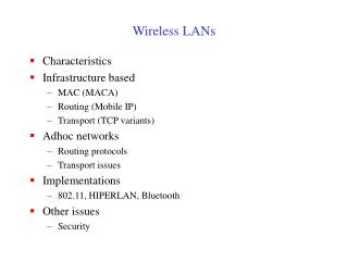
Wireless LANs. LAN/WLAN World. LANs provide connectivity for interconnecting computing resources at the local levels of an organization Wired LANs Limitations because of physical, hard-wired infrastructure Wireless LANs provide Flexibility Portability Mobility Ease of Installation.


Wireless LANs
E N D
Presentation Transcript
Wireless LANs Behrouz A. Forouzan” Data communications and Networking
LAN/WLAN World • LANs provide connectivity for interconnecting computing resources at the local levels of an organization • Wired LANs • Limitations because of physical, hard-wired infrastructure • Wireless LANs provide • Flexibility • Portability • Mobility • Ease of Installation
Wireless LAN Applications • Medical Professionals • Education • Temporary Situations • Airlines • Security Staff • Emergency Centers
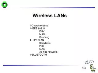
IEEE 802.11 Wireless LAN Standard • In response to lacking standards, IEEE developed the first internationally recognized wireless LAN standard – IEEE 802.11 • IEEE published 802.11 in 1997, after seven years of work • Scope of IEEE 802.11 is limited to Physical and Data Link Layers.
Benefits of 802.11 Standard • Appliance Interoperability • Fast Product Development • Stable Future Migration • Price Reductions • The 802.11 standard takes into account the following significant differences between wireless and wired LANs: • Power Management • Security • Bandwidth
IEEE 802.11 Terminology • Access point (AP): A station that provides access to the DS. • Basic service set : a set is of stationary or mobile wireless stations and an optional central base station, known as the access point (AP). • Distribution system (DS): A system used to interconnect a set of BSSs to create an ESS. • DS is implementation-independent. It can be a wired 802.3 Ethernet LAN, 802.4 token bus, 802.5 token ring or another 802.11 medium. • Extended service set (ESS):Two or more BSS interconnected by DS • extended service set uses two types of stations: mobile and stationary • The mobile stations are normal stations inside a BSS. The stationary stations are AP stations that are part of a wired LAN.
WLAN Topology Ad-Hoc Network The BSS without an AP is a stand-alone network and cannot send data to other BSSs. they can locate one another and agree to be part of a BSS.
WLAN Topology Infrastructure EX: cellular network if we consider each BSS to be a cell and each AP to be a base station.
Distribution of Messages • Distribution service (DS) • Used to exchange MAC frames from station in one BSS to station in another BSS • When BSSs are connected, the stations within reach of one another can communicate without the use of an AP. • Note that a mobile station can belong to more than one BSS at the same time
Station Types IEEE 802.11 defines three types of stations based on their mobility in a wireless LAN: • no-transition A station is either stationary (not moving) or moving only inside a BSS • BSS-transition station can move from one BSS to another, but the movement is confined inside one ESS. • and ESS-transition mobility. A station can move from one ESS to another
IEEE 802.11 Medium Access Control • MAC layer covers three functional areas: • Reliable data delivery • Access control • Security
MAC Sublayer IEEE 802.11 defines two MAC sublayers: • the distributed coordination function (DCF). • and point coordination function (PCF).
MAC Sublayer • Distributed Coordination Function (DCF) • Distributed access protocol • Contention-Based • Makes use of CSMA/CA rather than CSMA/CD for the following reasons: • Wireless LANs cannot implement CSMAfCD for three reasons: 1. For collision detection a station must be able to send data and receive collision signals at the same time( costly stations and increased bandwidth requirements). 2. Collision may not be detected because of the hidden station problem. 3. The distance between stations may result in Signal fading which prevent a station at one end from hearing a collision at the other end. • Suited for ad hoc network and ordinary asynchronous traffic
CSMAICA in wireless LAN 1. station senses the medium (checking the energy level at carrier frequency): a. uses a persistence strategy with back-off until the channel is idle. b. if idle channel , waits for of time called distributed interframe space (DIFS); then sends a request to send (RTS) Control frame . 2. the destination station receive RTS and waite for short interframe space (SIFS), than send clear to send (CTS) control frame,(ready to receive data) 3. The source station sends data after waiting an amount of time equal to SIFS. 4. The destination station, after waiting for time equal to SIFS, sends an acknowledgment
collision avoidance CSMAICA • network allocation vector (NAV) used to avoid collision. • RTS frame includes the duration of time that it needs to occupy the channel. • stations affected by this transmission create a timer called (NAV) • the network allocation vector (NAV) shows the time must pass before these stations allowed to check the channel for idleness. • there is no mechanism for collision detection, if the sender has not received a CTS frame from the receiver, assumes there has been a collision ,the sender tries again.
MAC Sublayer • Point Coordination Function (PCF) • an optional access method on top of DCF • Implemented in an infrastructure network (not in an ad hoc network). • Contention-Free • mostly for time-sensitive transmission services like voice or multimedia. • The AP performs polling stations one after another, sending any data they have to the AP.
MAC Sublayer • To give priority to PCF over DCF, another set of interframe spaces has been defined: • SIFS - Short Inter Frame Spacing • Used for immediate response actions e.g ACK, CTS • PIFS - Point Inter Frame Spacing • PIFS (PCF IFS) is shorter than the DIFS. • if, at the same time, a station wants to use only DCF and an AP wants to use PCF, the AP has priority.
MAC Sublayer • Repetition interval has been designed to cover both contention-free (PCF) and contention-based (DCF) traffic to allow DCF accessing the media. • The repetition interval starts with control frame, called a beacon frame. • When the stations hear the beacon frame, they start their NAV for the duration of the contention-free period of the repetition interval.
MAC Sublayer • repetition interval used by the PC (point controller) stations. • At the end of the contention-free period, the PC sends a CF end (contention-free end) frame to allow the contention-based stations to use the medium.
Fragmentation • The wireless environment is very noisy. • corrupt frame has to be retransmitted. • Fragmentation is recommended. • the division of a large frame into smaller ones. • It is more efficient to resend a small frame than a large one.
MAC Frame Format • The MAC layer frame consists of nine fields
MAC Frame Format • Frame control : 2 bytes long and defines the type of frame and some control information. • D: In all frame types except one, this field defines the duration of the transmission that is used to set the value of NAV. In one control frame, this field defines the frame ID. • Addresses: There are four address fields, each 6 bytes long. The meaning of each address field depends on the value of the To DS and From DS subfields .
MAC Layer Frames • Sequence control: This field defines the sequence number of the frame to be used in flow control. • Frame body: This field can be between 0 and 2312 bytes, it contains information based on the type and the subtype defined in the FC field. • FCS: The FCS field is 4 bytes long and contains a CRC-32 error detection sequence.
Frame Types • IEEE 802.11 has three categories of frames: • management frames: used for the initial communication between stations and access points. • control frames. used for accessing the channel and acknowledging frames • data frames. Data frames are used for carrying data and control information.
Addressing Mechanism • IEEE 802.11 addressing mechanism specifies four cases defined by the value of the two flags in the FC field, To DS and From DS.
Addressing Mechanism • Case 1: 00, To DS = 0 and From DS = 0 • This means that the frame is not going to a distribution system and is not coming from a distribution system. • The ACK frame should be sent to the original sender. • Case 2: 01, In this case, To DS = 0 and From DS = 1. • This means that the frame is coming from a distribution system (coming from an AP ). • The ACK should be sent to the AP. The addresses are as address 3 contains the original sender of the frame (in another BSS).
Addressing Mechanism • Case 3: 10, To DS =1 and From DS =O. • This means that the frame is going to a distribution system ( frame is going from a station to an AP) • The ACK is sent to the original station. address 3 contains the final destination of the frame (in another BSS). • o Case 4:11, To DS =1 and From DS =1. • This is the case in which the distribution the frame is going from one AP to another AP in a wireless distribution system. • We do not need to define addresses if the distribution system is a wired LAN because the frame in these cases has the format of a wired LAN frame (Ethernet, for example). • Here, we need four addresses to define the original sender, the final destination, and two intermediate APs.
Industrial-Scientific-Medical (ISM) band • The 2.4GHz ISM band is divided into 79 bands of 1MHz
Physical layer of IEEE 802.11 FHSS • In Frequency Hopping Spread Spectrum (FHSS) the sender sends on one carrier frequency for a short amount of time, then hops to another carrier frequency for the same amount of time, and so on. After N hop-pings, the cycle is repeated. • Spreading makes it difficult for unauthorized persons to make sense of the transmitted data
Physical layer of IEEE 802.11 DSSS • In Direct Sequence Spread Spectrum (DSSS) each bit sent by the sender is replaced by a sequence of bits called a chip code. • To avoid buffering, the time needed to send one chip code must be the same as the time needed to send one original bit. • DSSS is implemented at the physical layer and uses a 2.4GHz ISM band
Physical layer of IEEE 802.11a OFDM • IEEE 802.11a describes the orthogonal frequency-division multiplexing (OFDM) method for signal generation in the 5GHz ISM band • OFDM is the same as FDM with one major difference: • All the subbands are used by one source at a given time • Sources conend with one another at the data link layer for access • OFDM uses PSK (18Mbps) and QAM (54Mbps) for modulation
Physical layer of IEEE 802.11b • IEEE 802.11b describes the high-rate DSSS method for signal generation at 2.4GHz ISM band. • This is similar to DSSS except for the encoding method, which is called complementary code keying (CCK) • CCK encodes 4 or 8 bits to one CCK symbol
Physical Media Defined by Original 802.11 Standard • IEEE 802.11 FHSS(Frequency-hopping spread spectrum) • Operating in 2.4 GHz ISM band • Lower cost, power consumption • Most tolerant to signal interference • IEEE 802.11 DSSS (Direct-sequence spread spectrum) • Operating in 2.4 GHz ISM band • Supports higher data rates • More range than FH or IR physical layers • IEEE 802.11 Infrared • Lowest cost • Lowest range compared to spread spectrum • Doesn’t penetrate walls, so no eavesdropping
IEEE 802.11a , IEEE 802.11b and IEEE 802.11g • IEEE 802.11a • Makes use of 5-GHz band • Provides rates of 6, 9 , 12, 18, 24, 36, 48, 54 Mbps • Uses orthogonal frequency division multiplexing (OFDM) • IEEE 802.11b • 802.11b operates in 2.4 GHz band • Provides data rates of 5.5 and 11 Mbps • Complementary code keying (CCK) modulation scheme • IEEE 802.11g • 802.11g operates in 2.4 GHz band • Provides data rates of 22 and 54 Mbps • Uses orthogonal frequency division multiplexing (OFDM)
BLUETOOTH • Bluetooth is a wireless LAN technology designed to connect devices of different functions such as telephones, notebooks, computers, cameras, printers, coffee makers, and so on. A Bluetooth LAN is an ad hoc network, which means that the network is formed spontaneously. • Bluetooth defines two types of networks: piconet and scatternet.
Piconet • A Bluetooth network is called a piconet, or a small net. • It can have up to eight stations, one of which is called the master; the rest are called slaves. • Maximum of seven slaves. Only one master. • Slaves synchronize their clocks and hopping sequence with the master. • But an additional eight slaves can stay in parked state, which means they can be synchronized with the master but cannot take part in communication until it is moved from the parked state.
Scatternet • Piconets can be combined to form what is called a scatternet. • A slave station in one piconet can become the master in another piconet. • Bluetooth devices has a built-in short-range radio transmitter.
Bluetooth layers • Radio Layer: Roughly equivalent to physical layer of the Internet model. Physical links can be synchronous or asynchronous. • Uses Frequency-hopping spread spectrum [Changing frequency of usage]. Changes it modulation frequency 1600 times per second. • Uses frequency shift keying (FSK )with Gaussian bandwidth filtering to transform bits to a signal. • Baseband layer: Roughly equivalent to MAC sublayer in LANs. Access is using Time Division (Time slots). • Length of time slot = dwell time = 625 microsec. So, during one frequency, a sender sends a frame to a slave, or a slave sends a frame to the master. • Time division duplexing TDMA (TDD-TDMA) is a kind of half-duplex communication in which the slave and receiver send and receive data, but not at the same time (half-duplex). However, the communication for each direction uses different hops, like walkie-talkies.
Single-secondary communication • Also called Single-slave communication • Master uses even-numbered slots • Slave uses odd-numbered slots
Multiple-secondary communication Also called Multiple-slave communication • Master uses even-numbered slots • Slave sends in the next odd-numbered slot if the packet in the previous slot was addressed to it.
Physical Links • Synchronous connection-oriented (SCO) • Latency is important than integrity. • Transmission using slots. • No retransmission. • Asynchronous connectionless link (ACL) • Integrity is important than latency. • Does like multiple-slave communication. • Retransmission is done. • L2CAP (Logical Link Control and Adaptation Protocol) • Equivalent to LLC sublayer in LANs. • Used for data exchange on ACL Link. SCO channels do not use L2CAP. • Frame format has 16-bit length [Size of data coming from upper layer in bytes], channel ID, data and control. • Can do Multiplexing, segmentation and Reassembly, QoS [with no QoS, best-effort delivery is provided] and Group mangement [Can do like multicast group, using some kind of logical addresses].
SUMMARY • The wireless LAN access method is CSMA/CA. • The network allocation vector (NAV) is a timer for collision avoidance. • The MAC layer frame has nine fields. The addressing mechanism can include up to four addresses. • Wireless LANs use management frames, control frames, and data frames. • Bluetooth is a wireless LAN technology that connects devices (called gadgets) in a small area. • A Bluetooth network is called a piconet. Multiple piconets form a network called a scatternet. • The Bluetooth radio layer performs functions similar to those in the Internet model's physcial layer. • The Bluetooth baseband layer performs functions similar to those in the Internet model's MAC sublayer. • A Bluetooth network consists of one master device and up to seven slave devices. • •A Bluetooth frame consists of data as well as hopping and control mechanisms. A frame is one, three, or five slots in length with each slot equal to 625 μs.