Download
1 / 46
460 likes | 481 Vues
Dive deep into UML diagrams and models, learn how to analyze and apply them effectively in software development for requirements engineering. Explore the history of UML and key diagram types for reliable system modeling.

E N D
SEG3101 (Fall 2018) Requirements Modelling with UML 2 Daniel Amyot, University of Ottawa Based on Powerpoint slides by Gunter Mussbacher with material from: B. Selic, Brugge & Dutoit, developpez.com, S. Somé 2008, D. Amyot 2008-2018, et G.v. Bochmann 2010
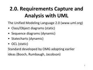
Overview • Models and Analysis • UML for Requirements Engineering • UML Class Diagrams for Domain Models • UML State Diagrams for lifecycles
All models are false, but some models are useful… • George Edward Pelham Box (1919-2013)
Models • According to Bran Selic, a model is a reduced representation (simplified, abstract) of (one aspect of) a system used to: • Help understand complex problems and / or solutions • Communicate information about the problem / solution • Direct implementation (especially in software) • Qualities of a good model • Abstract • Understandable • Accurate • Predictive • Inexpensive
Natural language (English) No special training required Ambiguous, verbose, vague, obscure ... No automation Ad hoc notation (bubbles and arrows) No special training required No syntax formally defined meaning not clear, ambiguous No automation Semi-formal notation (URN, UML...) Syntax (graphics) well defined Partial common understanding, reasonably easy to learn Partial automation Meaning only defined informally Still a risk of ambiguities Formal notation (Logic, SDL, Petri nets, FSM ...) Syntax & semantics defined Great automation (analysis and transformations) More difficult to learn & understand Modeling Representations
Model Analysis • By construction • We learn by questioning and describing the system • By inspection • Execute/analyze the model in our minds • Reliable? • By formal analysis • Requires formal semantics (mathematical) and tools • Reliable (in theory), but expensive (for certain modeling approaches) • By testing • Execution, simulation, animation, test... • Requires well-defined semantics and execution/simulation tools • More reliable than inspection for certain aspects • Possible to interact directly with the model (prototype)
History of UML (http://www.omg.org/uml/) Rumbaugh Booch Jacobson http://www.omg.org/uml/ Official Version 2.5 (June 2015) “Simplified”… only 794 pages! Source: http://en.wikipedia.org/wiki/Unified_Modeling_Language
Thirteen Diagram Types in UML 2.x • According to UML Reference Manual • Structural • Class, object, composite structure, component, and use case diagrams • Dynamic (that is, describing dynamic behavior) • State machine, activity, sequence, communication, timing, and interaction overview diagrams • Physical • Deployment diagrams • Model Management • Package diagram
Most Relevant for Requirements Engineering • Use case diagram • Use cases structuring • Activity diagram • Workflow and process modeling • Concepts much related to concepts of Use Case Maps • Sequence diagram • Modeling of message exchange scenarios • Class diagram • Domain modeling • State machine diagram • Detailed behavioral specification (of objects, protocols, ports…) • System behaviour (black box) • Object/document lifecycles
Basic Notational Elements of Activity Diagrams • Describe the dynamic behavior of a system as a flow of activities (workflow) • Flow • Sequence • Alternative • Parallel • Note: in this diagram, the data flow objects are not shown. They may be shown as boxes on the control flow lines.
UCM or UML Activity Diagrams? • UCM and Activity Diagrams have many concepts in common • Responsibility action, start/end points, alternatives, concurrency • Stub / plug-in action / sub-activity diagram • Association between elements and components / partition • Unique to Activity Diagrams • Data flow modeling, with rich data • Integration with UML (including class diagrams and OCL) • Unique to UCM • Dynamic stubs with several plug-ins • Plug-ins can continue in parallel with their parent model • 2D graphical layout of components • Definitions of scenarios (integrated testing capabilities) • Integration with GRL in URN
Basic Notational Elements of Sequence Diagrams • Describe the dynamic behavior as interactions between so-called “participants” (e.g. agents, actors, the system, system components). For each participant, there is a “lifeline” http://fox.wikis.com/graphics/sequence.gif
Combined Fragments • Allow multiple sequences to be represented in compact form (may involve all participants or just a subset) • Combined fragment operators • alt, for alternatives with conditions • opt, for optional behavior • loop(lower bound, upper bound), for loops • par, for concurrent behavior • critical, for critical sections • break, to show a scenario will not be covered • assert, required condition • ignore/consider(list of messages), for filtering messages • neg, for invalid or mis-use scenarios that must not occur • strict or seq, for strict/weak sequencing • ref, for referencing other sequence diagrams
Concurrency Quiz • Is the interaction on the right a valid sequential trace that can be generated from the interaction with the par combined fragment on the left? • No! The sequences of the two operands may be interleaved but the ordering defined for each operand must be maintained.
From ER to Class Diagrams • Based on Entity-Relationship modeling • Originally proposed by Peter Chen in 1976 • Concepts: • Entity/Class: represents a type of entity instances, defines the properties that hold for all such instances. • Relationship/Association: represents relationship that hold between certain pairs of entities. • The related entity types are also called roles. • Multiplicity information indicate how many instances of the “other” side may be related to a given instance of “this” side. • Attribute: An entity may have attributes. Each attribute is identified by a name and its (data/class) type
Class Diagrams for Domain Modeling • It is important to define • The concepts that exist in a domain where requirements are being specified • Provides the basic terminology/vocabulary • The particular attributes of these concepts • The relationships that exist between these concepts • Generalization, aggregation, others more domain-specific… • Class diagrams are ideal to capture this information! • But a precise subset is useful here…
Class Diagrams for Precise Domain Modeling • No operations! • Attributes with types • Use associations when types are other classes • Associations with precise multiplicities • Beware of fixed numbers… and of 1..1 associations! • Names for association ends (roles) must be used instead of a simple association name • Less confusing, especially for expressing constraints • Enumerations are also useful • Beware of generalization • Yes, patterns are useful here too! • Supplement with constraints for precision wherever needed • In natural language (using the names of classes, attributes, and association ends in the model) or in OCL (Object Constraint Language)
Exercise… • Design a simple domain model for a genealogy software application • What are the relevant classes, attributes and associations? • Do you see some constraints that are difficult to express with UML class diagrams?
ComponentA R1 elements ComponentD R1 elements ComponentC R1 elements ComponentE ComponentB R1 elements Requirement1 (R1) Requirement2 (R2) Requirement3 (R3) ComponentF R1 elements R2 elements R3 elements RN elements … RequirementN (RN) Modularity Problems with Class Diagrams (Info) Scattering: designelements to support R1 in many components Tangling: single component has elements for many requirements
intertypedeclaration Aspect advice ClassA R1 elements ClassC R1 elements ClassG R1 elements ClassB R1 elements pointcut ClassF R1 elements R2 elements R3 elements RN elements (identifies joinpointswhere advice is executed) A Partial Solution – Aspects (info) R1 elements F.R1 Triggered behavior (code) R1 elements Predicate R1 elements R1 elements R1 elements Terminology based on AspectJ: www.eclipse.org/aspectj
Basic Notational Elements of State Machine Diagrams • Describe the dynamic behavior of an individual object (with states and transitions)
on on Lamp On Lamp On print(”on”) on on/print(”on”) off off off off Lamp Off Lamp Off Moore Automaton Mealy Automaton Types of State Machines • UML allows both types to be mixed
on Lamp On on/ctr := ctr + 1 off off Lamp Off Variables (“Extended” States) ctr : Integer
threshold time Modeling Behavior • In general, state machines are suitable for describing reactive systems based or events • Not appropriate to describe continuous systems (e.g., spacecraft trajectory control, stock market predictions)
top stop UML State Machine Diagrams – Summary Composite State State Initial Pseudostate Trigger Ready Transition stop /ctr := 0 Done Final State Action
LampOn e2 e1 Entry and Exit Actions entry/lamp.on(); exit/lamp.off();
LampOn LampOff entry/lamp.on(); off/printf(“to off”); entry/lamp.off(); exit/printf(“exiting”); exit/printf(“exiting”); off/printf(“needless”); Action Ordering • Output actions: transition prefix • Input actions: transition postfix Resulting action sequence: printf(“exiting”); printf(“to off”); lamp.off(); printf(“exiting”); printf(“needless”); lamp.off();
Error entry/printf(“error!”) State Activity (Do) • Creates a concurrent process that will execute until • The action terminates, or • We leave the state via an exit transition “do” activity do/alarm.ring()
bid [value < 100] /reject Selling bid [value >= 200] /sell Happy bid [(value >= 100) & (value < 200)] /sell Unhappy Guards (Conditions) • Conditional execution of transitions • Guards must not have side effects
flash/ LampOn LampOff off/ entry/lamp.on() entry/lamp.off() 1sec/ 1sec/ on/ on/ FlashOn FlashOff on/ entry/lamp.off() entry/lamp.on() Hierarchical State Diagrams • Composed states, to manage complexity LampFlashing
flash/ LampOff LampOn off/ entry/lamp.off() entry/lamp.on() 1sec/ 1sec/ on/ FlashOff FlashOn on/ entry/lamp.off() entry/lamp.on() Group Transitions Default transition to Initial pseudostate LampFlashing Group transition
Committing Phase1 CommitDone Phase2 Completion Transition • Triggered by a completion event • Automatically generated when an embedded state machine terminates Completion transition (without trigger)
on/ on/ Triggering Rules • Many transitions can share the same triggering event • When leaving, the most deeply embedded one takes precedence • The event disappears whether it triggers a transition or not LampFlashing FlashOn off/ FlashOff
S1 exit/exS1 S2 entry/enS2 S11 exit/exS11 S21 entry/enS21 Action Ordering – Composite States /initS2 E/actE Action sequence on transition E: exS11exS1 actE enS2 initS2 enS21
Exercise I – Describe this Behavior • What should be added to this state machine to more fully describe the dialing behavior?
age financialStatus Child Poor Adult age financialStatus Rich Child Retiree Poor Adult Rich Retiree Orthogonal Regions • Combine many concurrent perspectives – interactions across regions typically done via shared variables
legalStatus financialStatus LawAbiding Poor robBank/ robBank/ Outlaw Rich Semantics of Orthogonal Regions • All mutually orthogonal regions detect the same events and respond simultaneously (possibly interleaved)
CourseAttempt Studying lab done lab done Lab1 Lab2 project done Term Project pass Final Test fail Failed Passed Exercise II – Describe this Behaviour
Exercise III • In requirements engineering, state machines are quite popular for describing the lifecycle of documents and other artefacts. • Simpler subset of the notation needed • States, transitions with events [and conditions] • Fewer actions than for conventional behaviour descriptions • Hierarchical states and orthogonal regions used only if they simplify the model • Simple but still VERY useful! • Using a UML state machine diagram, describe the lifecycle of: • A software bug in a bug management system such as Bugzilla or Jira. • An prerequisite exemption request for a course at the University of Ottawa.
Quiz! • Is formal logic always better than natural language? • Why do we need domain models in requirements engineering? • Why must class diagrams be sometimes supplemented by constraints? • Why are Hierarchical State Diagrams useful? • Why spend time documenting lifecycles of documents and objects?