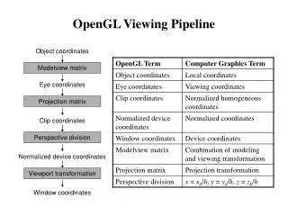
Viewing in OpenGL
CSC 341 Introduction to Computer Graphics. Viewing in OpenGL. Viewing. Perspective Projection: When objects are farther from the viewer their images become smaller Real looking All projectors meet at center of projection ( COP)

Viewing in OpenGL
E N D
Presentation Transcript
CSC 341 Introduction to Computer Graphics Viewing in OpenGL
Viewing • Perspective Projection: • When objects are farther from the viewer their images become smaller • Real looking • All projectors meet at center of projection ( COP) • Parallel Projection : all projectors are parallel to each other • main one: Orthographic Projection • simplest, default • Center of projection is replaced by a direction of projection • No distortion of distance or shape
Recall perspective projection: side view • Camera pointing along positive z-axis • The center of projection (COP) is at the origin (0,0,0) • Film plane located at distance d from the pinhole • Film plane is at z = -d • is projection of -d
z=0 Orthographic Viewing In the default orthographic view, points are projected forward along the z axis onto the plane z=0 Orthographic projection takes (x,y,z) and projects to (x,y,0)
In OpenGL • We have the choice of perspective camera or orthogonal camera • Two main steps in viewing • Position the camera • Job of modelview matrix • After vertices pass through this transformation, they are represented in camera coordinates • Apply orthographic or perspective projection • We shall examine these steps
Steps • We assume that all objects are initially represented relative to a standard 3D coordinate frame, in what are called world coordinates • Step1: Modelview Transformation • Maps vertices from their world coordinates to one that is relative to the camera: Camera Coordinates • Step2: Perspective/Orthographic Projection: • Project points in 3D camera coordinates to points on viewing plane:Normalized Device Coordinates • Step3: Map from viewplane to viewport: Pixel(Viewport) Coordinates
Default OpenGL Camera • OpenGL places a camera on the projection plane at the origin pointing in the negative z direction • Set for orthographic views • The default viewing volume is a box centered at the origin with a side of length 2 objects within the volume is visible • Both modelview and projection matrices are default: Identity
Transform Objects = Transform Camera • Recall: Transformations were altering the Modelview matrix • Default: Modelview matrix is identity: world frame and camera frame is same • If Modelview matrix is altered: there could be two ways of looking at this: • (1) Camera changed its location and frame • (2) camera still at the same location but objects moved.
In rotating cube example • We rotated the cube to see all faces • Alternatively, we could have rotated the camera (in reverse direction!)
Positioning the camera • We will start considering the first view: position the camera • One way of positioning the camera is doing transformations (as we have seen) to alter modelview matrix accordingly, but this is not very intuitive • We will describe another way: • Describe camera’s position and orientation with respect to the world frame. Define “camera frame” • In OpenGL, there is a nice utility for this: gluLookAt(…) let’s you specify camera’s position and orientation and computes the matrix M to transform world coordinates to camera coordinates, and multiplies M with The Current Modelview Matrix C (alters modelview matrix!)
Order • Conceptually change of coordinates is performed after all Modelview transformations and before projection. • After all projection is easier to describe when camera is at origin) • Recall perspective projection assumed, camera at origin and pointing in –z direction. • Reverse Rule: of transformations: gluLookAt(…) should be the first to be specified after glLoadIdentity()
Typical calling sequence glLoadIdentity(); gluLookAt(eyeX,eyeY,eyeZ, atX, atY, atZ, upX, upY, upZ) //all parameters of gluLookAt are GLdouble //all other Modelview transformations follow this. • Eye = [eyeX, eyeY, eyeZ ] is a point, denoting the location of the camera/eye/viewer • At = [atX, atY, atZ ] is a point used to indicate the direction that the camera is pointed • View = normalize(At – Eye) defines the view vector, camera can still rotate around view vector, so we will fix it using up vector • Up=[upX, upY, upZ ] is a vector that defined what is “up” of the camera
Up vector • Up vector cannot be parallel to View vector • it need not be perpendicular to viewing vector, either.
Camera Frame • OpenGL uses these arguments to gluLookAt to define the camera frame • Centered at Eye (origin of the camera frame) • X-axis directed toward right • Y-axis directed toward up • Z-axis in opposite direction of view vector • Let C.O, C.x, C,y and C.z denote the origin and basis vectors of the camera frame
Camera Frame • Right-handed coordinate system • Cross product of u and v is perpendicular to both u and v and is directed according to the right hand rule
gluLookAt glLookAt(eyex, eyey, eyez, atx, aty, atz, upx, upy, upz)
Building the Camera Frame • OpenGL decided to stick with right-handed system so C.z is opposite direction of viewing • We will construct an orthonormal frame: all basis vectors are unit and orthogonal to each other • C.O = Eye // origin at eye • C.z = -View • Where View = normalize(At-Eye) • C.x? • Should be orthogonal to C.z and up vector • And, should be directed towards camera’s right
C.x • C.x = normalize (View X Up) • C.y? • Should be orthogonal to C.x and C.z
C.y • C.y = C.z X C.x • Now we can construct the change of coordinates Matrix M to convert from standard frame F to camera frame C • Recall M is the matrix whose columns are the basis elements of C relative to F
DefaultProjection Default projection is orthogonal clipped out 2 z=0
Projections and Normalization • The default projection in the eye (camera) frame is orthogonal • For points within the default view volume • Most graphics systems use view normalization • All other views are converted to the default view by transformations that determine the projection matrix • Allows use of the same pipeline for all views xp = x yp = y zp = 0
Homogeneous Coordinate Representation xp = x yp = y zp = 0 wp = 1 default orthographic projection pp = Mp M =
Simple Perspective • Center of projection at the origin • Projection plane z = d, d < 0
Perspective Equations Consider top and side views xp = yp = zp = d
Homogeneous Coordinate Form consider q = Mp where M = p = q =
Perspective Division • However w 1, so we must divide by w to return from homogeneous coordinates • This perspective division yields the desired perspective equations • We will consider the corresponding clipping volume with the OpenGL functions xp = yp = zp = d
OpenGL Orthogonal Viewing glOrtho(xmin,xmax,ymin,ymax,near,far) glOrtho(left,right,bottom,top,near,far) nearandfarmeasured from camera
OpenGL Perspective glFrustum(xmin,xmax,ymin,ymax,near,far)
Using Field of View • With glFrustum it is often difficult to get the desired view • gluPerpective(fovy, aspect, near, far) often provides a better interface front plane aspect = w/h