Download
1 / 15
150 likes | 349 Vues
EUS Meeting 4 November 2004. Grazing-incidence design and others. L. Poletto Istituto Nazionale per la Fisica della Materia (INFM) Department of Electronics and Informatics - Padova (Italy). slit. spectrometer. telescope. detector. Performance evaluation of any spectroscopic design.

E N D
EUS Meeting4 November 2004 Grazing-incidence design and others L. Poletto Istituto Nazionale per la Fisica della Materia (INFM) Department of Electronics and Informatics - Padova (Italy)
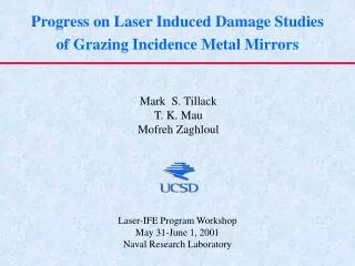
slit spectrometer telescope detector Performance evaluation of any spectroscopic design Three optical parameters are calculated in the evaluation of the performance: 1) the spatial resolution in the direction perpendicular to the slit 2) the spatial resolution in the direction parallel to the slit 3) the spectral resolution PARAMETER NO. 1 DEPENDS ONLY ON THE OPTICAL PROPERTIES OF THE TELESCOPE PARAMETERS NO. 2 DEPENDS ON THE PERFORMANCE OF THE WHOLE INSTRUMENT (TELESCOPE + SPECTROMETER) PARAMETERS NO. 3 DEPENDS ON THE PERFORMANCE OF THE SPECTROMETER
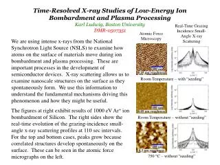
The grazing-incidence Wolter telescope Grazing-incidence telescope two concave mirrors (parabola and hyperbole) and a plane mirror rastering: rotation of the plane mirror CHARACTERISTICS 58-63 nm spectral region 18 arcmin 18 arcmin field-of-view length <1 m
Grazing-incidence design: characteristics Telescope Wolter II Focal length1200 mm Incidence angles 72 deg - 74 deg Slit Size 6 mm 6.3 mm Resolution 1 arcsec Grating TVLS Groove density 3600 lines/mm Entrance arm 300 mm Exit arm 900 mm Spectral region 58-63 nm Detector Pixel size 9 mm 18mm Format 2200 1100 pixel Spectral resolving element 28 mÅ (14 km/s) Spatial resolving element 1 arcsec (150 km at 0.2 AU) Instrument length 1000 mm
Efficiency at 60 nm Total efficiency at wavelength l ETOT(l) = A [cm2] E(l) PS [arcsec2] AEF entrance aperture E(l) combined efficiency (telescope, spectrometer, detector) at wavelength l PS pixel size CDS on SOHO, NIS2 channelETOT_CDS(60 nm) = 0.046 Grazing-incidence design at 60 nm AEF = 25 cm2 = 5 cm × 5 cm Si-Au coated optics Rmirrors = 0.62, 0.67, 0.78 Egrating = 0.15 Edetector = 0.30 ETOT(60 nm) = 0.36 = 8 TIMES CDS EFFICIENCY Normal-incidence design at 60 nm AEF = 25 cm2 SiC optics Rmirror = 0.30 (high thermal absorption in the visible and near IR) The same efficiency as the GI design is obtained with AEF = 25 cm2 = 5 cm × 5 cm Au optics Rmirror = 0.12 (low thermal absorption) The same efficiency as the GI design is obtained with AEF = 65 cm2 = 8 cm × 8 cm
Thermal load: GI versus NI Grazing-incidence configuration: 5 cm × 5 cm Thermal load 85 W Power absorption on the mirrors 42 W - 20 W (3.3 - 3.7 solar constants) Power density on the slit plane 4 solar constants (f = 1200 mm) Normal-incidence configuration: SiC optics, 5 cm × 5 cm Thermal load 85 W Power absorption on the mirror 54 W (16 solar constants) Power density on the slit plane 16 solar constants (f = 600 mm) Normal-incidence configuration: Au optics, 8 cm × 8 cm Thermal load 218 W Power absorption on the mirror 35 W (10 solar constants) Power density on the slit plane 170 solar constants (f = 600 mm)
Some considerations on the entrance filter • As proposed in the Astrium Payload Integration Study, an entrance filter could reduce to zero the thermal load on the optics. • A suitable filter for the 60 nm region is a thin Al foil (200 nm, 0.6 transmission) • VERY RISKY SOLUTION: single point failure • FEASIBLE ? • Grazing-incidence configuration • The filter is on the entrance aperture • Thermal load on the filter • 25 solar constants on the Al foil • Normal-incidence configuration • The filter is inserted at the end of the entrance tube (0.8 m) • 20 solar constants on the Al foil • NO FILTER AVAILABLE ABOVE 90 NM
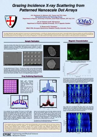
Alternative configuration: GI grating + NI design The thermal load on the focusing optics is reduced to zero if the visible and near IR radiation is deflected by a suitable first optical element out of the entrance aperture of the mirror. THE DIVISION BETWEEN THE EUV RADIATION AND THE VISIBLE RADIATION IS PERFORMED BY A PLANE DIFFRACTION GRATING ON THE ENTRANCE
Alternative configuration: characteristics Entrance aperture Size50 mm × 70 mm Grating Incidence angle75 deg Groove density 360 gr/mm Coating Au Size 195 mm × 70 mm Rastering Grating rotation Telescope Parabola Focal length650 mm Incidence angle 1.5 deg Size 30 mm × 70 mm Slit Size 5.2 mm 0.9 mm Resolution 1 arcsec Grating TVLS Groove density 4800 lines/mm Entrance arm 150 mm Exit arm 930 mm Magnification 6.2 Size 10 mm 20 mm Dispersion 0.16 nm/mm Spectral region 58-63 nm Detector Pixel size 17.5 mm 5mm Format 1780 1100 pixel Spectral resolving element 28 mÅ (14 km/s) Spatial resolving element 1 arcsec (150 km at 0.2 AU) Instrument length 950 mm
Alternative configuration: efficiency at 60 nm Total efficiency at wavelength l ETOT(l) = A [cm2] E(l) PS [arcsec2] AEF entrance aperture E(l) combined efficiency (telescope, spectrometer, detector) at wavelength l PS pixel size CDS on SOHO, NIS2 channelETOT_CDS(60 nm) = 0.046 Alternative configuration AEF = 35 cm2 Egrating_1 = 0.35 Rmirror = 0.30 Egrating_2 = 0.15 Edetector = 0.30 ETOT(60 nm) = 0.16 = 3.5 TIMES CDS EFFICIENCY
Alternative configuration: thermal load Entrance aperture: 5 cm × 7 cm Thermal load 120 W Power absorption on the grating 15 W (0.8 solar constant) 105 W can be simply rejected out of the instrument through a suitable aperture only 15 W absorbed NO THERMAL LOAD ON THE TELESCOPE
Alternative configuration: experimental observations Two wavelengths from the same spatial region are dispersed by the first grating and imaged by the telescope in different zones on the entrance slit plane. THE SAME SPATIAL REGION IS OBSERVED AT DIFFERENT WAVELENGTHS IN DIFFERENT IMAGES (SO IN DIFFERENT TIMES) ON THE SAME IMAGE, EVERY WAVELENGTH COMES FROM A DIFFERENT SPATIAL REGION OF THE SUN
Alternative configuration: conclusions ADVANTAGES No thermal load on the telescope, entrance slit and grating The coatings on the optics can be optimized for any spectral region in the EUV (15-150 nm) Only 15 W have to be dissipated DRAWBACKS The efficiency is lower than the NI or GI configurations, but anyway higher than CDS The same spatial region is observed at different wavelengths in different times This effect can be mitigated by using multiple entrance slits OBSERVATION The requested resources (mass and envelope) can be minimized by a close integration with other instruments