Download
1 / 32
330 likes | 468 Vues
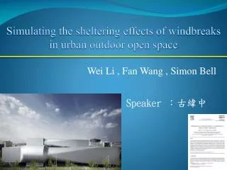
Simulating the sheltering effects of windbreaks in urban outdoor open space. Wei Li , Fan Wang , Simon Bell. Speaker :古緯中. Introduction Wind tunnel experiment Numerical Result and analyses. Introduction. Introduction. Windbreaks. Buildings. Introduction.

E N D
Simulating the sheltering effects of windbreaks in urban outdoor open space Wei Li , Fan Wang , Simon Bell Speaker :古緯中
Introduction • Wind tunnel experiment • Numerical • Result and analyses
Introduction Windbreaks Buildings
Introduction A common feature of these studies is that the windbreaks are considered in a fully open space, such as an area of countryside, with no obstruction in its vicinity or else such objects are so small relative to the size of the windbreaks that their influence is negligible. In a built-up area of an urban environment, however, the presence of buildings can no longer be ignored.
Wind tunnel experiment 2.1 Wind tunnel and models The boundary layer wind tunnels in Building Research Establishment Ltd. (BRE) and Heriot-Watt University (HWU) are both capable of simulating the atmospheric boundary layer at approximately 1:150–1:400 scales. Calibration for the speed measuring of the hot wires was made at the beginning of each day of measurement or at every change of probes.
Wind tunnel experiment 2.1 Wind tunnel and models
Wind tunnel experiment 2.1 Wind tunnel and models 1 : 200
Wind tunnel experiment 2.2 Wind flow profile
Numerical simulation 3.1 Modeling the windbreak The mean momentum equation by Hoerner (1965) :resistence coeffocoent :porosity
Numerical simulation 3.2 Governing equations The drag force For the narrow vegetative or artificial windbreak, the porosity or penetrability is equivalent to the optical porosity, which can be acquired by taking black–white pictures behind a windbreak and counting the percentage of the white area.
Numerical simulation 3.3 Turbulence models The KE model The KE modelis by far the most widely used two-equation turbulence model. The KE-two-layer (KE-2L) model The KE-two-layer (KE-2L) modeis the revised KE model, which uses the high-Reynolds-number KE model only in the fully turbulent region, away from the wall, and the near-wall viscosity-affected layer is resolved with a one-equation model. The KE-RNG The KE-RNG is calculated by re-normalization group (RNG) methods giving somewhat different values.
Numerical simulation 3.4 Discretization schemes The finite-volume method (FVM) was used to discretize the governing equations, about which there are several kinds of differencing schemes. • The HYBRID differencing scheme • The QUICK differencing scheme • The SMART difference scheme
Numerical simulation 3.4 Discretization schemes The HYBRID differencing schis based on a combination of central and upwind differencing schemes. The HYBRID differencing scheme The QUICK differencing scheme uses a three-point upstream-weighted quadratic interpolation for cell face values. It has greater formal accuracy than the central, upwind or HYBRID scheme. The QUICK differencing scheme The SMART difference scheme, as one of the non-linear schemes attempts to adapt the discretization to avoid the unwanted behaviour of the (QUICK) linear schemes, such as the unboundness. The SMART difference scheme
Numerical simulation 3.5 Boundary conditions • Symmetrical conditions to lateral and top boundaries. • (2) Outflow conditions (no re-entry and no variable gradient) to outlet. • (3) Log-law wind speed profile to the inlet with k (turbulent kinetic energy) measured from wind tunnel experiments and ε (dissipation rate) calculated from k. • (4) Smooth wall conditions to the ground and surfaces of buildings and windbreaks.
Result and analyses 4.1 The validation of CFD simulations At this stage, the first half of this study, simulation of the simplified built environment, one building and one tree belt, has been fully investigated in terms of the selection of turbulence models, the numerical schemes and the grid density.
Result and analyses 4.1.1 On the turbulence models
Result and analyses 4.1.2 On the dscretization schemes The best The worst
Result and analyses 4.1.3 On the simulation of windbreak-only case
Result and analyses 4.1.3 On the simulation of windbreak-only case From our simulation, a good agreement with the experiment has been achieved in the lee right behind the windbreak (within 8H). That the simulation working with KE-2L model and SMART scheme gave better description to the flow within and very close to the windbreak.
Result and analyses 4.1.4 On the incoming wind directions
Result and analyses 4.2.1 The wind flow regimes
Result and analyses 4.2.1 The wind flow regimes
Result and analyses 4.2.2The difference of porosity
Result and analyses 4.2.3 The difference of distance When the distance was less than 4H, the standing vortex in front of the building dominated the lower part of the flow field. If the distance exceeded 4H, the penetrability of the fence became very important, or equivalent to the effect of the presence of the building.
Result and analyses 4.2.3 The difference of distance
Result and analyses 4.2.4 On the effect of vertical porosity variation
Result and analyses 4.2.5 On the effect of the height of the building
Conclusion and future works The changes of the flow regimes have been revealed both in CFD simulations and wind tunnel experiments (Figs. 5 and 10a). If windbreaks are not far away from buildings, e.g. within 4– 5H (windbreak’s height), the distance between them is the governing factor for the wind speed reduction, instead of the porosity of the windbreak. CFD simulations wind tunnel experiments
Conclusion and future works To reduce wind speed on large areas, high-density windbreaks (20–30% porosity) should be given the first consideration in landscaping when buildings are sited at a short distance from windbreaks. For the numerical simulations, the KE-2L turbulence model would be a better choice for simulating airflow around windbreaks.