Download
1 / 49
490 likes | 512 Vues
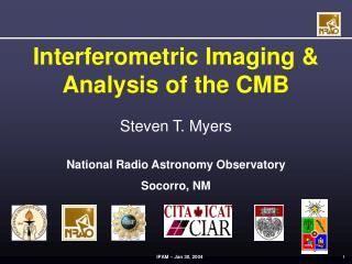
The I13L Project: Microscopic Imaging and Coherence and the CXRD capabilities at Diamond. C. Rau. Introduction Science Considerations Project. Introduction. I13L a long beamline at DIAMOND for imaging and coherence related experiments Two branches with canted undulators:

E N D
The I13L Project:Microscopic Imaging and Coherenceand the CXRD capabilities at Diamond C. Rau Introduction Science Considerations Project
Introduction • I13La long beamline at DIAMOND for imaging and coherence related experiments • Two branches with canted undulators: ‘Imaging’: high resolution imaging in real space ‘Coherence’: reciprocal space imaging Relation between both?
Introduction Timeline budget, etc. Project started June 2007 (with me) Technical Design Report August 2008 First user April 2011 End of budget December 2011 -> Project without delay! Budget : ~4M£ for beamline and ~2M£ for external building Personel : 1 Principal Beamline Scientist, 1 Second BLSc, 2 Support Sc (I hope) + Techn. Staff
Purpose of I13 Perform and promote high resolution imaging / tomography beyond today’s limits Techniques either in direct or reciprocal space Applications for broad user community: Bio-medical , materials science, archeology etc.
Imaging in real space: In-line phase contrast imaging (micro-Scale) Imaging in reciprocal space: Coherent Diffraction Pattern of BaTiO3 fibre, 180nm diameter Gerbil CochleaStudy of hearing BTO(002) Data has potential for 5nm resolution Full-field microscopy (nano-Scale) Photonic Crystal(hollow spheres in Ni matrix) Corresponding X-ray microscope image:sample mounted on W tip BTO(001) 1µm
Science related to 1µm
Scientific Applications for I13 Bio-medical imaging: Cochlea • Goal: imaging of cochlea structureand dynamics • In-situ study, preservation of cochlea functionality • Conventional methods lack eitherspatial resolution/sensitivity (NMR) or don’t preserve integrity of sample (e-microscopy) • Imaging with hard X-rays is adequate • Both soft tissue and strongly absorbing material present • Sample amount for Classical Sectioning
Instrumentation: In-line Phase contrast imaging X-Rays z • Detector resolution: 1µm • Small source, long distancecoherent radiation • In-line phase contrast imaging/tomography • Energy range:6-12keV (at 34ID-C / APS) • High quality stages: Rotation Stage air bearing (run out<20nm)
Bio-medical imaging: Slice of cochlea In-line phase contrast Light microscopy Ref.: C. Rau et al., Microscopy Research and Technique, 69(8), 660-665, 2006. • Hair cells transform movement into electrical signal • Imaging of slice – real cochlea?
Tomography: visualize Slice under real conditions Volume information but limited field of view
Science related to 50 nm
Full-field microscope (34ID-C APS) Sample Undu- lator Mirror Mono Condenser Objective 2-D detector 53 m 20 cm 10 cm 53.1 m 2.5 cm 50-100 cm -Similar to visible light microscope -KB: high efficiency -FZP: high resolution -Condenser matches aperture of objective lens Camera KB Sample FZP
Nano Science: Photonic Crystals ‘Optical Guide’ Materials with ‘Photonic Gap’ Structure-Properties Hollow Spheres in Ni void • 50 nm Resolution • contrast ~10% 1µm
Imaging in direct space • ‘Real space imaging’ limited by: • Detector resolution • X-ray optics • Source size (projection microscopy) • limit ~ 10nm for full-field imaging? • - Reciprocal space imaging promising
Science related to 5 nm and finer…
Fourier Transform Coherent Diffraction from Crystals Slice court. R. Harder
K Fourier Transform H Coherent Diffraction from Crystals Slice court. R. Harder
3D Diffraction Method Silver Nano Cube (111) CCD kf ki Q=kf-ki Yugang Sun and Younan Xia, Science 298 2177 (2003) Slice court. R. Harder
3D Ag Nano Cube Yugang Sun and Younan Xia, Science 298 2177 (2003) Slice court. R. Harder
Simultaneous Full-Field Microscopy and Coherent X-Ray Diffraction of BaTiO3 Nano-Wire • Orientation of sample • Input for CXRD reconstruction • High Resolution of CXRD data • CXRD data → 5nm resolution BTO(001) BTO(002) Ref.: R. Harder, in preparation.
Particularities I13L Long straight section (8m) at I 13 -> canted undulators independent operating stations -> option for mini-beta Long beamline ; external building
Why a long beamline • Reasons to build a long beamline: • Coherence length (lateral) • Scanning Microscopy with a long working distance • USAXS • XPCS • Imaging with large field of view • In addition some things become simpler with available space…
Coherence • Longitudinal coherence ~Nn N : number of undulator periods n : undulator harmonic -> exotic concepts • Lateral coherence lat =lD/2ss: source size, D:distance • I13 is a long section (8m) : space for 4m undulator dedicated for coherence + 2m for imaging • Concept long beamline vs. intermediate focus • With distance increase lateral coherence length but total coherent flux depends only on source parameter and undulator • Beam splitting [for upgrade]
CXRD • High coherent photon flux • Focusing on small crystals with • Long working distance • Stable and reliable Diffractometer • Energy ~8keV • Detector • Multiplexing OK
How to classify proposals? • ‘Coherence’:very clean parallel beamlong Undulator with many periodsE ~ 8keV • ‘Imaging’ flux important E~ 20keV shorter Undulator* * space sharing …
Overview Experimental Stations Mono may be close to experimental hutch
Upgrade Options Beam splitting coherence branchfor dedicated USAXS
Optics • Keep it simple! • Avoid dynamic optics • ‘Coherence’:Si 111/311 Mono, LN2 cooled (alternative water?) option pink beam Flat mirrors with different coating stripes planar lenses for collimation etc. [USAXS: ‘half’ Bonse-Hart Optic with multi-bounce Si311]
Coherence branch • Horizontal deflecting mirror: suppress higher harmonics, Bremsstrahlung, branch separation • Mono (changed!) rather horizontal deflecting, close to experiment: stability, heatload density,
Optics ‘Imaging’:Si 111/Multilayer, LN2 cooled (alternative water?) option pink beam Flat mirrors with different coating stripes planar lenses for poss. Intermediate focus
Imaging branch • Horizontal deflecting mirror: suppress higher harmonics, Bremsstrahlung • Mono Si(111) and Multilayer close to source: spatial filtering • Stability with intermediate focusing?
Mini-beta Long straight divided into two ‘mini-beta’ • Small betax ->close gap, high E • Slope of betax: Beam in first (‘left’) section focus in ‘A’ • Focus may be close to FE • Matching coherence lengths A B. Singh, R. Bartolini, R. Walker
Mini-beta Mini – beta Long straight sx min= 90mm ; sx’= 32mrad sy min= 7mm ; sy’= 5-6mrad sx=180mm ; sx’=18mrad sy= 13mm ; sy’= 3mrad - ‘Astigmat’ source - Matching of coherence lengths - higher divergence - Smaller Undulator Gap simulations by U. Wagner
Undulator U20 Undulator with 5mm (blue) and 7mm(red) gap
Branches Coherence Branch • Energy (wavelength) range : 6-20 keV • Band-pass (DE/E) : 10-4 (mono) or 10-2 (pink) • Beam size at sample : 1.5x8.6mm2 • Photon flux : 7x10¹⁴ Ph/s/0.1%BW at 8keV Imaging Branch • Energy (wavelength) range : 8-30 keV • Band-pass (DE/E) : 10-4 (mono) or 10-2 (pink) • Beam size at sample : 1.5x6.4mm2 • Photon flux : 1014 Ph/s/0.1%BW at 20keV
Floorplan internal - overview X-rays Control Cabin Optics for two branches and space for later upgrades Drawing provided by A. Peach
Floorplan external building Labs Imaging CCs X-Rays Mono Coherence Detector Infrastructure 5m • - Stability and space: long hutches on piles • Concrete Hutches built together building -> costs • Second floor: Offices and ‘Open access’ area Drawing provided by A. Peach
In-line phase contrast -µm resolution -easy to use -large field of view 6µm Cone-beam imaging -sub-µm resolution -dose efficient -sub-100nm source -elaborate data reconstruction 2µm Full-field microscope - 50nm resolution - imaging of phase objects 2µm Imaging hutch 6µm In-line phase contrast -µm resolution -easy to use -large field of view 2µm Cone-beam imaging -sub-µm resolution -dose efficient -sub-100nm source -elaborate data reconstruction 2µm • Full-field microscope • - 50nm resolution • imaging of phase objects • combined methods Full-field imaging with different spatial resolution
Coherence hutch CDI with collimated beam • Beside CXRD: • XPCS • Coherent Diffraction Imaging techniques • similar setup (Det. in transm.) • user community • scientific life • laser facility at Harwell Site CDI with focused beam Graphs courtesy I. McNulty
Detectors • Direct space/ Imaging CCD coupled via microscope optics to a scintillation screen Key elements: scintillation screens & detector Option FreLoN camera • Reciprocal space / Coherence Direct detection Speed Dynamic range ‘Intelligent’ design (e.g. integrated auto-correlator) DIAMOND is likely to join MEDIPIX/MAXIPIX program other solutions
Acknowledgements DIAMOND: U. Wagner : Optics & Discussions A. Peach: Drawings M. Launchbury & M. Smith : Project Management I.Robinson : Discussions ALL people from UWG for discussions!
Full-field Microscopy/Imaging • Flux • Reasonable divergence • Full-field microscopy: ‘Köhler’ divergence • In-line phase contrast : reasonable divergent source • Option: secondary source • Energy ~20keV • Temperature stability of hutch • Short distances OK • Long distance to increase field of view
DISCUSSION Concept long beamline vs intermediate focus Both are valid
DISCUSSION Concept long beamline vs intermediate focus • Conlusion: “Coherence only” experiments -> long BL+ “long” undulator + splitting “Some/partial” coherence ->short BL + intermediate foc. + “short” undulator In addition I believe nobody has the ultimate answer…