OpenGL: Simple Use
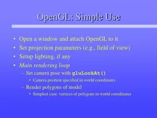
OpenGL: Simple Use. Open a window and attach OpenGL to it Set projection parameters (e.g., field of view) Setup lighting, if any Main rendering loop Set camera pose with gluLookAt() Camera position specified in world coordinates Render polygons of model

OpenGL: Simple Use
E N D
Presentation Transcript
OpenGL: Simple Use • Open a window and attach OpenGL to it • Set projection parameters (e.g., field of view) • Setup lighting, if any • Main rendering loop • Set camera pose with gluLookAt() • Camera position specified in world coordinates • Render polygons of model • Simplest case: vertices of polygons in world coordinates
Creating Geometry • All geometry composed of vertices (points) • ‘Primitive type’ defines the shape they describe • Example vertices: glVertex (x, y, z, w) • glVertex2d - z coordinate is set to 0.0 • glVertex3d - w coordinate is set to 1.0 • glVertex4d - all coordinates specified (rarely done)
Primitive Types • GL_POINTS • GL_LINE • {S | _STRIP | _LOOP} • GL_TRIANGLE • {S | _STRIP | _FAN} • GL_QUAD • {S | _STRIP} • GL_POLYGON
GL_POLYGON • List of vertices defines polygon edges • Polygon must be convex
Non-planar Polygons • Imagine polygon with non-planar vertices • Some perspectives will be rendered as concave polygons • These concave polygons may not rasterize correctly
Generating Primitives • Primitive defined within glBegin() and glEnd() • Very few GL commands can be executed within these two GL calls • Any amount of computation can be performed glBegin (GL_LINE_LOOP); for (j=0; j<10; j++) { angle = 2*M_PI*j/10; glVertex2f (cos(angle), sin(angle)); } glEnd();
OpenGL: More Examples • Example: GL supports quadrilaterals: glBegin(GL_QUADS); glVertex3f(-1, 1, 0); glVertex3f(-1, -1, 0); glVertex3f(1, -1, 0); glVertex3f(1, 1, 0); glEnd(); • This type of operation is called immediate-mode rendering; each command happens immediately
OpenGL: Front/Back Rendering • Each polygon has two sides, front and back • OpenGL can render the two differently • The ordering of vertices in the list determines which is the front side: • When looking at thefront side, the vertices go counterclockwise • This is basically the right-hand rule
OpenGL: Drawing Triangles • You can draw multiple triangles between glBegin(GL_TRIANGLES) and glEnd(): float v1[3], v2[3], v3[3], v4[3]; ... glBegin(GL_TRIANGLES); glVertex3fv(v1); glVertex3fv(v2); glVertex3fv(v3); glVertex3fv(v1); glVertex3fv(v3); glVertex3fv(v4); glEnd(); • Each set of 3 vertices forms a triangle • What do the triangles drawn above look like? • How much redundant computation is happening?
OpenGL: Triangle Strips • An OpenGL triangle strip primitive reduces this redundancy by sharing vertices: glBegin(GL_TRIANGLE_STRIP); glVertex3fv(v0); glVertex3fv(v1); glVertex3fv(v2); glVertex3fv(v3); glVertex3fv(v4); glVertex3fv(v5); glEnd(); • triangle 0 is v0, v1, v2 • triangle 1 is v2, v1, v3 (why not v1, v2, v3?) • triangle 2 is v2, v3, v4 • triangle 3 is v4, v3, v5 (again, not v3, v4, v5) v2 v4 v0 v5 v1 v3
Polygon Rendering Options • Rendered as points, lines, or filled • Front and back faces can be rendered separately using glPolygonMode( ) • glPolygonStipple( ) overlays a MacPaint-style overlay on the polygon • glEdgeFlag specifies polygon edges that can be drawn in line mode • Normal vectors: normalized is better, but glEnable(GL_NORMALIZE) will guarantee it
Polygonalization Hints • Keep orientations (windings) consistent • Best to use triangles (guaranteed planar) • Keep polygon number to minimum • Put more polygons on silhouettes • Avoid T-intersections to avoid cracks • Use exact coordinates for closing loops E BAD OK B B D A A C C
OpenGL: Specifying Normals • Calling glNormal() sets the normal vector for the following vertices, till next glNormal() • So flat-shaded lighting requires: glNormal3f(Nx, Ny, Nz); glVertex3fv(v0);glVertex3fv(v1);glVertex3fv(v2); • While smooth shading requires: glNormal3f(N0x, N0y, N0z); glVertex3fv(v0); glNormal3f(N1x, N1y, N1z); glVertex3fv(v1); glNormal3f(N2x, N2y, N2z); glVertex3fv(v2); • (Of course, lighting requires additional setup…)
OpenGL: Specifying Color • Calling glColor() sets the color for vertices following, until the next call to glColor() • To produce a single aqua-colored triangle: glColor3f(0.1, 0.5, 1.0); glVertex3fv(v0); glVertex3fv(v1); glVertex3fv(v2); • To produce a Gouraud-shaded triangle: glColor3f(1, 0, 0); glVertex3fv(v0); glColor3f(0, 1, 0); glVertex3fv(v1); glColor3f(0, 0, 1); glVertex3fv(v2); • In OpenGL, colors can also have a fourth component (opacity) • Generally want = 1.0 (opaque);
OpenGL: Specifying Viewpoint glMatrixMode(GL_MODELVIEW); glLoadIdentity(); gluLookAt(eyeX, eyeY, eyeZ, lookX, lookY, lookZ, upX, upY, upZ); eye[XYZ]: camera position in world coordinates look[XYZ]: a point centered in camera’s view up[XYZ]: a vector defining the camera’s vertical • Creates a matrix that transforms points in world coordinates to camera coordinates • Camera at origin • Looking down -Z axis • Up vector aligned with Y axis
Translations • For convenience we usually describe objects in relation to their own coordinate system • We can translate or move points to a new position by adding offsets to their coordinates: • Note that this translates all points uniformly
Scaling • Scaling a coordinate means multiplying each of its components by a scalar • Uniform scaling means this scalar is the same for all components: 2
X 2,Y 0.5 Scaling • Non-uniform scaling: different scalars per component: • How can we represent this in matrix form?
Scaling • Scaling operation: • Or, in matrix form: scaling matrix
2-D Rotation (x’, y’) (x, y) x’ = x cos() - y sin() y’ = x sin() + y cos()
2-D Rotation x = r cos (f) y = r sin (f) x’ = r cos (f + ) y’ = r sin (f + ) Trig Identity… x’ = r cos(f) cos() – r sin(f) sin() y’ = r sin(f) sin() – r cos(f) cos() Substitute… x’ = x cos() - y sin() y’ = x sin() + y cos() (x’, y’) (x, y) f
2-D Rotation • This is easy to capture in matrix form: • 3-D is more complicated • Need to specify an axis of rotation • Simple cases: rotation about X, Y, Z axes
3-D Rotation • What does the 3-D rotation matrix look like for a rotation about the Z-axis? • Build it coordinate-by-coordinate
3-D Rotation • What does the 3-D rotation matrix look like for a rotation about the Y-axis? • Build it coordinate-by-coordinate
3-D Rotation • What does the 3-D rotation matrix look like for a rotation about the X-axis? • Build it coordinate-by-coordinate
3-D Rotation • General rotations in 3-D require rotating about an arbitrary axis of rotation • Deriving the rotation matrix for such a rotation directly is a good exercise in linear algebra • Standard approach: express general rotation as composition of canonical rotations • Rotations about X, Y, Z
Composing Canonical Rotations • Goal: rotate about arbitrary vector A by • Idea: we know how to rotate about X,Y,Z • So, rotate about Y by until A lies in the YZ plane • Then rotate about X by until A coincides with +Z • Then rotate about Z by • Then reverse the rotation about X (by -) • Then reverse the rotation about Y (by -)
Composing Canonical Rotations • First: rotating about Y by until A lies in YZ • How exactly do we calculate ? • Project A onto XZ plane (Throw away y-coordinate) • Find angle to X: = -(90° - ) = - 90 ° • Second: rotating about X by until A lies on Z • How do we calculate ?
Composing Canonical Rotations • Why are we slogging through all this tedium? • A: Because you’ll have to do it on the test
3-D Rotation Matrices • So an arbitrary rotation about A composites several canonical rotations together • We can express each rotation as a matrix • Compositing transforms == multiplying matrices • Thus we can express the final rotation as the product of canonical rotation matrices • Thus we can express the final rotation with a single matrix!
Compositing Matrices • So we have the following matrices: p: The point to be rotated about A by Ry : Rotate about Y by Rx : Rotate about X by Rz : Rotate about Z by Rx -1: Undo rotation about X by Ry-1: Undo rotation about Y by • In what order should we multiply them?
Compositing Matrices • Short answer: the transformations, in order, are written from right to left • In other words, the first matrix to affect the vector goes next to the vector, the second next to the first, etc. • So in our case: p’ = Ry-1 Rx -1 Rz Rx Ry p
Rotation Matrices • Notice these two matrices: Rx : Rotate about X by Rx -1: Undo rotation about X by • How can we calculate Rx -1?
Rotation Matrices • Notice these two matrices: Rx : Rotate about X by Rx -1: Undo rotation about X by • How can we calculate Rx -1? • Obvious answer: calculate Rx (-) • Clever answer: exploit fact that rotation matrices are orthonormal
Rotation Matrices • Notice these two matrices: Rx : Rotate about X by Rx -1: Undo rotation about X by • How can we calculate Rx -1? • Obvious answer: calculate Rx (-) • Clever answer: exploit fact that rotation matrices are orthonormal • What is an orthonormal matrix? • What property are we talking about?
Rotation Matrices • Orthonormal matrix: • orthogonal (columns/rows linearly independent) • normalized (columns/rows length of 1) • The inverse of an orthogonal matrix is just its transpose:
Modeling Transformations • glTranslate (x, y, z) • Multiplies the current matrix by a matrix that moves the object by the given x-, y-, and z-values • glRotate (theta, x, y, z) • Multiplies the current matrix by a matrix that rotates the object in a counterclockwise direction about the ray from the origin through the point (x, y, z)
Modeling Transformations • glScale (x, y, z) • Multiplies the current matrix by a matrix that stretches, shrinks, or reflects an object along the axes.
Matrix Multiplcations • Certain commands affect the current matrix in OpenGL • glMatrixMode() sets the current matrix • glLoadIdentity() replaces the current matrix with an identity matrix • glTranslate()postmultipliesthe current matrix with a translation matrix • gluPerspective() postmultipliesthe current matrix with a perspective projection matrix • It is important that you understand the order in which OpenGL concatenates matrices
Matrix Operations In OpenGL • In OpenGL: • Vertices are multiplied by the MODELVIEW matrix • The resulting vertices are multiplied by the projection matrix • Example: • Suppose you want to scale an object, translate it, apply a lookat transformation, and view it under perspective projection. What order should you make calls?
Matrix Operations in OpenGL • Problem: scale an object, translate it, apply a lookat transformation, and view it under perspective • A correct code fragment: glMatrixMode(GL_PERSPECTIVE); glLoadIdentity(); gluPerspective(…); glMatrixMode(GL_MODELVIEW); glLoadIdentity(); gluLookAt(…); glTranslate(…); glScale(…); /* Draw the object... */
Matrix Operations in OpenGL • Problem: scale an object, translate it, apply a lookat transformation, and view it under perspective • An incorrect code fragment: glMatrixMode(GL_PERSPECTIVE); glLoadIdentity(); glTranslate(…); glScale(…); gluPerspective(…); glMatrixMode(GL_MODELVIEW); glLoadIdentity(); gluLookAt(…); /* Draw the object... */
Multiplication Order glMatrixMode (MODELVIEW); glLoadIdentity(); glMultMatrix(N); glMultMatrix(M); glMultMatrix(L); glBegin(POINTS); glVertex3f(v); glEnd(); Modelview matrix successively contains: I(dentity), N, NM, NML The transformed vertex is: NMLv = N(M(Lv))
Multiplication Order • Rotate line segment by 45 degrees about endpoint Wrong Right R(45) T(-3), R(45), T(3) OpenGL T(3) R(45) T(-3)
Manipulating Matrix Stacks • Observation: Certain model transformations are shared among many models • We want to avoid continuously reloading the same sequence of transformations • glPushMatrix ( ) • push all matrices in current stack down one level and copy topmost matrix of stack • glPopMatrix ( ) • pop the top matrix off the stack
Matrix Manipulation - Example • Drawing a car with wheels and lugnuts draw_wheel( ); for (j=0; j<5; j++) { glPushMatrix (); glRotatef(72.0*j, 0.0, 0.0, 1.0); glTranslatef (3.0, 0.0, 0.0); draw_bolt ( ); glPopMatrix ( );