Pulsed Fiber Laser Autocorrelator
140 likes | 346 Vues
Pulsed Fiber Laser Autocorrelator. Matthew Wilson and Gabe Trippel. What Is Optical Autocorrelation?. A way to measure a femtosecond laser pulse Uses a second-order response (nonlinear) amplified by constructive interference Defined by convolution of electric field of two different paths

Pulsed Fiber Laser Autocorrelator
E N D
Presentation Transcript
Pulsed Fiber Laser Autocorrelator Matthew Wilson and Gabe Trippel
What Is Optical Autocorrelation? • A way to measure a femtosecond laser pulse • Uses a second-order response (nonlinear) amplified by constructive interference • Defined by convolution of electric field of two different paths A(t) ≡ ʃ E(t)E*(t - Δt) dt + = (constructive part only)
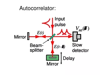
How it works… • Uses Michelson interferometer • Laser pulses constructively interfere when Michelson arm lengths are equal • Requires second order response detection P(t) = ɛ0(χ(1)E(t) +χ(2)E2(t) + …) (polarization density) • Achieved by… • SHG with nonlinear crystal …or… • Two-photon absorption • Amplitude of nonlinear signal is proportional to intensity:
Pulsed Fiber Laser System From Wesley Hughes and Jared Green’s Presentation
Signal Detection System • Observed Nonlinear Response of IR Fiber Laser: • For Both Standard Silicon Diode (FDS100, ThorLabs) and Avalanche Photo Diode (AD500, Pacific Silicon Sensors) • Requires small beam diameter on detector to increase probability of Two Photon Absorption • d = λf/∏D D = Diameter of Beam d = diameter of focused spot size f = focal length • Also obtained the Gain Curves for : • 532nm Diode Laser, HeNe Laser, and IR Pulsed Fiber Laser
Gain of Avalanche Photo Diode Gain = (APD Output) / (ADP Output at 1V)
APD Output vs Bias Voltage for Pulsed Fiber Laser • No signal below 90V Reversed Bias • No External Amplification on APD (yet)
Interferometer Diagram and Picture • Beam Chopper included between Beam Splitter and Speaker • Top and Bottom Arm’s are chopped at different frequencies Mirror Mirror Beam Splitter Speaker w/ Corner Cube Chopper Concave Lens Laser Convex Lens’s Mirror Mirror Mirrors and Lenses are maximized for IR
Data Acquisition Linear Response measured with InGaAs Detector and Continuous Wave 1550nm IR Diode Laser Speaker Off Speaker On (1 Hz)
Nonlinear Response! Nonlinear Response from 1550 nm IR Erbium Doped Pulsed Fiber Laser • Beam Passed through Interferometer then Focused onto Avalanche Photo Diode (APD) • Gain: G ≈ 25 internal to APD at 135V, plus external gain from LT1028 op-amp Beam Blocked Beam Unblocked Beam Blocked Beam Un-Blocked Response Visible on APD Output (Lock-In Amp not able to Lock onto signal)
Future Investment What can help to Complete Project: • InGaAs and Silicon (layered) Detector • Allows Observation of Linear & Nonlinear Response Simultaneously (for easier signal capture/maximization) • Automatic single-axis translational stage for one Michelson arm • Because human arms get tired • XYZ translation mount for Detector • For Signal Optimization • More Powerful Laser
New techniques for laser pulse measurement: • FROG – Frequency Resolved Optical Gating • Similar to autocorrelation, but gets more info • Asymmetries resolved (chirp, satellite pulses) FROG trace: • SPIDER – Spectral Phase Interferometry for Direct Electric field Reconstruction • Uses spectral shearing Both techniques require a spectrometer and special software. (Other “swamp” techniques: BOA Compression, SEA TADPOLE, MIIPS, and more…)