Understanding Interstellar Magnetic Fields: Insights from the Solar Vicinity
350 likes | 465 Vues
This presentation explores the local interstellar magnetic field (ISMF) and its implications for the heliosphere. Key topics include the influence of the ISMF on solar wind termination shocks encountered by Voyager spacecraft, the equilibrium of magnetic and gas pressures in the local interstellar medium (ISM), and the direction of the ISMF derived from various astronomical observations. The findings suggest the Sun resides in a superbubble fragment, highlighting the need for magnetic field explanations of heliospheric characteristics and the detection of energetic neutral atoms.

Understanding Interstellar Magnetic Fields: Insights from the Solar Vicinity
E N D
Presentation Transcript
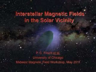
Interstellar Magnetic Fieldsin the Solar Vicinity P. C. Frisch et al. University of Chicago Midwest Magnetic Field Workshop, May 2011
et al….. B-G Andersson, SOFIA, USRA, CA Andrei Berdyugin, Tuorla Observatory, University of Turku, Finland Daiane Breves Seriacopi, U. Sao Paulo, Brazil Herbert O. Funsten, Los Alamos National Laboratory, Los Alamos Antonio M. Magalhaes, Inst. de Astro., Geo. & Ciencias Atmos., U. Sao Paulo, Brazil David J. McComas, Southwest Research Institute, San Antonio, TX Vilppu Piirola, Tuorla Observatory, University of Turku, Finland Nathan A. Schwadron, University of New Hampshire, Durham, NH Jonathan D. Slavin, SAO-Harvard, Cambridge, MA Sloane J. Wiktorowicz, University of California, Berkeley
OUTLINE • Local interstellar magnetic field (ISMF) and our magnetically shaped heliosphere • Local ISMF from the IBEX Ribbon • Local ISMF strength if in magnetic and gas pressures are in equilibrium local ISM • Local ISMF direction from linearly polarized starlight • ISMF direction from Loop I radio continuum • ISMF direction from nearby pulsars • Implications: Kinematical and ISMF suggest Sun in superbubble fragment • Summary
The Heliosphereas a Gauge for Strength and Direction of ISMF
Sun and Local Interstellar Medium (LISM):The Sun is in an Intermediate Velocity Cloud system (Frisch, APOD; Frisch, Redfield, Slavin 2011)
Voyager 1 & 2 in Inner Heliosheath V1 crossed solar Wind termination Shock at 94 AU In 2004 Termination shock Asymmetry caused By angle between Interstellar (IS) gas And ISMF V2 crossed solar Wind termination Shock at 84 AU In 2007 Asymmetry of heliopause Shown by 5o offset between upwind IS Heo and Ho directions
Heliosphere as gauge of ISMF (Pogorelov et al. 2009) • MHD models of the heliosphere, with ions coupled to neutral H by charge exchange, predict the heliosphere configuration • Magnetic field needed to explain observed heliosphere properties • 10 AU difference between Voyager 1 crossing the termination shock 2004 at 94 AU and Voyager 2 crossing the termnation shock in 2007. • 5 degree offset between velocity vectors of interstellar Ho and Heo flow in heliosphere • Direction of subsonic solar wind flow in inner heliosheath from Voyager 2 data • 3 kHz emissions detected by both V1 and V2 from beyond the heliopause • IBEX Ribbon
Magnetically Shaped Heliosphere for three ISMF directions (Opher et al. 2009)
IBEX maps Energetic Neutral Atoms (ENAs) for energies 0.05-6 keV • IBEX measures energetic neutral atoms formed by charge-exchange between interstellar neutral Ho and solar wind and pickup ions (McComas et al. 2009 Science) • IBEX discovered ‘Ribbon’ of ENAs that is seen where the radial sightline is orthogonal to the ISMF as it drapes over the heliopause • Pickup ion (PUI) forms when 26 km/s interstellar Ho gives e- to solar wind ion • Mechanism creates slow PUI and fast neutral (ENA) • PUIs become suprathermal in inner heliosheath • Takes three years for 440 km/s solar wind ion or PUI to propagate to inner heliosheath, charge exchange with interstellar Ho , and return to be measured by IBEX at 1 AU
Flow of neutral interstellar gas through heliosphere creates pickup ions and energetic neutral atoms (ENAs) ENAs (A) PUI Pitch Angles heavily Scattered by turbulence ENAs ENAs (B) PUI Pitch Angles Ring-beam ISMF
Interstellar Boundary Explorer (IBEX) Spacecraft launched late 2008; Four ENA skymaps collected to date • Two huge aperture single pixel ENA cameras: • IBEX-Lo (~10 eV to 2 keV) • IBEX-Hi (~300 eV to 6 keV) • Simple sun-pointed spinner (4 rpm) (McComas et al. 2009, SSR)
IBEX skymaps of Energetic Neutral Atoms Galactic coords Ribbon only Ecliptic coords (Schwadron et al. 2011)
MHD heliosphere model of Pogorelov et al. (2009, ApJL) was Basis for Identifying Ribbon with locus of sightlines that are perpendicular To ISMF draping over the heliosphere • MHD model predated Ribbon discovery • Ribbon match where the ISMF leaves strongest imprint on the heliopause, for 10 AU outside of heliopause • Model ISM: • |B|=3 G • n(p+)=0.06 cm-3, n(Ho)=0.15 cm-3 • Model is multifluid MHD model with plasma and neutrals kinetically coupled (Schwadron et al. 2009)
Ribbon seen where sightline is perpendicular to ISMF Draping over the heliosphere, e.g. where “B-dot-R=0” (McComas et al. 2009) (Pogorelov et al. 2009)
Modeling the Origin of the Ribbon quantitatively(Heerikhuisen et al. 2010) • ENAs carry solar wind momentum outside of heliopause • New charge-change creates secondary pickup ions form outside of heliopause • Third charge-change creates ENAs traveling in all directions • These ENAs are seen by IBEX as a Ribbon if the PUIs maintain pitch angles of about 90 deg long-enough to form new ENA. • Florinski (2011) argues that magnetic turbulence isotropizes the PUI angular distribution quickly (few minutes) compared to time-scales of charge-exchange (2 years) • Gamaunov et al. (2011) argue that locally generated small scale turbulence (ion cyclotron waves,10-4 AU) marginally stabilizes pitch angles so that Ribbon forms.
Best heliosphere values forStrength and direction of ISMF shaping heliosphere • Method: Model ENA Ribbon (Heerikhuisen et al. 2010) • |B| = 3 G • Direction: l,b = 36o, 53o • (Ribbon arc center) • Large scale magnetic turbulence can inhibit the isotropization of pitch-angles due to small-scale turbulence, and stabilize pitch angles around pseudo-ring beam (G., Zhang et al. 2011) • Method: Center of Ribbon arc (Funsten et al. 2009) • Direction: l,b = 33o, 55o • Method: Model heliosphere asymmetries and H-He offset angle (Opher et al. 2008) • |B| = 5G • Direction: l,b = 15o±4o, 33o±6o
Strength of Local ISMF if gas and magnetic pressures are equal, =1
Obtain interstellar gas pressure at the heliosphere • Temperature of ISM at heliosphere derived from Ulysses observations of HeI 25 km/s flow inside of heliosphere (caveat: new IBEX results) • Predict the density of ISM at heliosphere from photoionization models (CLOUDY code, Slavin and Frisch 2008) • Local Interstellar Cloud (LIC) observed in UV towards CMa gives sight-line properties • Constrain with ISM data from inside and outside of heliosphere • Electron density from CII*/CII, MgI/MgII, HI and HeI • Local interstellar cloud in CMa sightline • Interstellar HeI inside heliosphere • Pickup ion data on Ne, Ar, He • ( Redfield Linsky 2011)
In circumheliospheric ISM B=2.7 G if thermal and magnetic pressures equal • Results: • n(HI)~0.19 cm-3, n(e)~0.07 cm-3 • He ~39% ionized, H ~25% ionized • If gas and magnetic pressures are equal, • ~1, then B=2.7 G • Weakness: • Need new HST data for Sirius, a much closer star (2.7 pc) • HeI temperature (and density) inside of heliosphere may change (e.g. new IBEXLO data) (Slavin and Frisch 2008)
Local Interstellar Magnetic Field Direction from Polarized Starlight
ISMF direction from weak linear polarization of nearby stars in galactic center hemisphere (discovered by Tinbergen, 1982) Polarized starlight of stars within D<500 pc Shows Loop I Configuration • Local Patch of dust covers of Loop I region; polarization ~0.02% • Nearest star in Tinbergen sample is 6 pc away towards heliosphere nose • 36 Oph has very efficient polarization per unit column density (compared to distant stars) • Most local ISM within 15 pcs • D < 30--40 pc test the ISM close to the heliosphere (Mathewson & Ford 1994) (Tinbergen 1982)
ISMF in North Polar Spur is traced by both synchrotron emission and stellar polarization caused by magnetically aligned interstellar dust Synchrotron emission polarized perpendicular to ISMF Therefore polarization vector from dust opacity is parallel to ISMF Interstellar dust is ~1% gas mass Polarizations are proportional to dust mass but depends on viewing angle, clumpiness of dust, and number of magnetic field directions in sightline If only one magnetic field direction in sightline, e.g. nearby stars, polarization more efficient. North Polar Spur synchrotron emission indicates polarization plane due to magnetically aligned interstellar dust is parallel to ISMF direction Polarized synchrotron emission Polarized starlight 820 MHz starlight (Data from Berkhuijsen (1973), Mathewson & Ford (1974), And Berdyugin, unpublished)
Method for Fitting a magnetic field to the polarization position angles • Assemble data on interstellar polarizations of stars within 40 pc T=5000-10000 K (Redfield and Linsky 2004)
Polarization Data used in Paper I • These data give interstellar polarizations of stars 5-40 pc away • Factor of 70 range in sensitivities of data used in first analyses • Frisch et al. (2011) - 1sigma >/= 0.003% (NOT and LNA) • Planet Pol (Bailey et al. 2010) - 1 sigma ~ 0.0004% • Wiktorowicz (in Frisch et al. 2010)- 1-sigma~0.0004% • Santos et al. (2010) - 1 sigma ~ 0.02% • Tinbergen (1982), Piirola (1977) - 1sigma~0.007% • IBEX Ribbon: IBEX-HI 1 keV ENAs, for fluxes > 1.5*mean flux Ecliptic coords. Galactic coords.
Method for Fitting a magnetic field to the polarization position angles • Assemble data on interstellar polarizations of stars within 40 pc • Select spatial subsample of data (stars within 90o of heliosphere nose) • Assume that the subsample polarizations trace a single ISMF direction • Systematically rotate polarization position angles into all possible directions for dipole field, and see which direction does the best job of aligning the polarization vectors with a meridian of the coordinate system • Minimize Fi to find ISMF direction Bi , eg minimize the mean of all position angles j for j stars for ISMF direction Bi : • Paper I: Weight all data points equally (because of S/N differences. 7. Paper II (in progress): Better spatial coverage of high S/N data so use weighted fits (factor = G(sigma,P))
Find best-fitting ISMF to polarization data by minimizing F=mean(|sin(PA)|) for all possible ISMF directions on sky • Paper I: Best fitting interstellar magnetic field direction from unweighted optical polarization data: • Galactic coordinates: L = 38o B=23o (+/- 35o) • Ecliptic coordinates: = 263o=37o (+/- 35o) • Paper II: Unweighted fit with new data • Results same, uncertainties smaller • Paper II: Weighted fit with new data (in preparation) • ISMF direction changes by 12o • Uncertainties larger • Galactic coordinates: L = 49o, B=28o • Ecliptic coordinates: = 260o, = 49o
Strength and direction of Local ISMF from four pulsars in third galactic quadrant, 130-300 pc away
B-direction from Pulsar measurements: Obtain ISMF direction and strength from ratio of pulsar Faraday rotation and dispersion measures • Four pulsars (130-300 pc) in third galactic quadrant where see low density ISM • |B|=3.3 G • ISMF field is directed up out of the ecliptic plane, or • towards L,B=5o,42o • towards =232o,18o • This direction is 22o from center of IBEX ENA Ribbon arc • B|| from ratio of pulsar rotation and dispersion measures: • Ref: Salvati 2010
Direction of Local ISMF obtained from spherically complete Loop I superbubble shell (e.g.North Polar Spur) consistent with ISMF directions from polarization data and IBEX Ribbon
Very Local ISMF direction determined from the Loop I radio continuum is consistent with other local ISMF directions Loop I fit with two magnetic superbubble Shells, S1 & S2 Sun in S1 shell ISMF governing shell geometry: L,B=71o±48o, 18o±48o ISMF direction of S1 shell agrees with other indicators of local ISMF direction (Frisch Mueller 2011) Wolleben (2007) modeled 1.3 GHz Loop I as two “S1” & “S2” subshells
Implication: Both local ISMF direction and cloud kinematicssuggest solar location in expanding Loop S1 (black dots). LSR velocity vectors ISMF direction suggests Sun in compressed S1 shell of expanding Loop I Kinematics of interstellar Clouds within 15 pc suggest Association with S1 shell
SUMMARY • Linearly polarized starlight traces interstellar magnetic field (ISMF) • Optical polarizations of stars within 40 pc gives ISMF direction near Sun. Direction ~30o from Ribbon ISMF direction if a dipole field • Some polarizations trace same ISMF as IBEX Ribbon • Astronomical data on nearest pulsars and radio continuum polarization give similar ISMF directions • Implications: Kinematical and magnetic field support hypothesis that Sun is inside of fragment of expanding superbubble shell
The general flow past the Sun of interstellar gas within 15 pc is clumpy and turbulent • Most nearby ISM is within 15 pc • LSR velocity of bulk flow past Sun is -17 ± 5 km/s from L,B=335o, -7o • Clouds fill 6% to 19% of close space • Warm and low density: • T=2,000--12,000 K • N=0.1-0.2 /cc • The velocity of interstellar HeI in the heliosphere (Witte 2004) disagrees by ~2 km/s with velocity of ISM in the upwind direction • Sun near edge of of a cloud • The magnetic field in the Tinbergen polarization patch could from a separate kinematical component than ISMF affecting heliosphere. Ref: Frisch, Redfield, Slavin ARAA 2011
Global ISMF near Sun related to solar position in the Local Bubble • Sun in very low density Local Bubble cavity (n<0.005 /cc). • Solar location inside of Local Bubble gives rise to easy expansion of supernova remnants, with swept-up magnetic field, into low density region around the Sun. • Loop I, formed by supernova in Scorpius-Centaurus, is one of these remnants. • All models of the North Polar Spur (or Loop I) supernova remnant place Sun in rim, if it is spherical. (Frisch, APOD)