Download
1 / 28
290 likes | 462 Vues
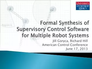
Formal Synthesis of Supervisory Control Software for Multiple Robot Systems. Jill Goryca, Richard Hill American Control Conference June 17, 2013. Outline. Background System Models Control Software Implementation Task Planning Algorithm Simulation Results Conclusion. Background. Goal:

E N D
Formal Synthesis of Supervisory Control Software for Multiple Robot Systems Jill Goryca, Richard Hill American Control Conference June 17, 2013
Outline • Background • System Models • Control Software Implementation • Task Planning Algorithm • Simulation Results • Conclusion
Background • Goal: • To control two or more robots that work together • Challenges: • Coordinate robot actions • Respond to changing goals and conditions • Scale small examples to larger ones • Practical applications: • Surveillance, search & rescue, and firefighting
Objective • Develop tools necessary to address complex scenarios • Tools include: • MATLAB Control Software • Task-Planning Optimization
Method • Apply supervisory control framework • Allow controllable and uncontrollable events • Assume all events are observable • Formally ensure safety and nonblocking • Use a relatively simple, but illustrative scenario involving control of two robots
Scenario Components: • 2 robots • 4 tasks • 4 regions Rules: • Complete all tasks • 1 before 2, same robot • 3 before 4, same robot • Different regions
System Model: Geography • Finite State Machine (FSM)represents region boundaries and task locations • One FSM for each robot • Initial location of robot is marked with an arrow (Robot A starts in region 5) Geographical Constraints
System Model: Task Constraints • Represents the rule that the robot must finish a task before it can start another one Task Contraints
System Model: Task Completion • Represents the order of task completion • Task 1 before task 2 by the same robot • Task 3 before task 4 by the same robot Task Completion
System Model: Avoidance • Represents the rule that robots may not be in the same region at the same time Avoidance
Supervisory Controller Model • Use UMDES/DESUMA software • Combine multiple FSMs to synthesize controller that meets goals • Contains 638 states and 1666 transitions • Text file format (*.fsm) is input to MATLAB control software
Control Software Architecture Finite State Machine User Input Interface MATLAB Tool Offline High-Level Control Online User Data Optimization (Calculate Costs, Dijkstra) Planner (Main Control File) Intermediary (Goal Plan, Detect Region Events) Low-Level Control (D*Lite, VFH, Mapping) Simulation (Player/Stage)
MATLAB Tool 2 1 3 4 5 6 8 7
User Data File Finite State Machine User Input Interface MATLAB Tool Offline High-Level Control Online User Data Optimization (Calculate Costs, Dijkstra) Planner (Main Control File) Intermediary (Goal Plan, Detect Region Events) Low-Level Control (D*Lite, VFH, Mapping) Simulation (Player/Stage)
User Data File • Script file generated from MATLAB Tool • Name of Initial and Final State • User Data matrices: • States—from FSM file • Events—from MATLAB Tool • Tasks—from MATLAB Tool • Regions—from MATLAB Tool
Planner: Main Control File Finite State Machine User Input Interface MATLAB Tool Offline High-Level Control Online User Data Optimization (Calculate Costs, Dijkstra) Planner (Main Control File) Intermediary (Goal Plan, Detect Region Events) Low-Level Control (D*Lite, VFH, Mapping) Simulation (Player/Stage)
Planner: Main Control File • MATLAB high-level control code • Written off-line • References User Data file generated by MATLAB Tool • Controls 1 robot • “While” loop completes “mission” of FSM • Executes optimal path through FSM • Receives events from both robots (when crossing borders and finishing tasks)
Intermediary Functions Finite State Machine User Input Interface MATLAB Tool Offline High-Level Control Online User Data Optimization (Calculate Costs, Dijkstra) Planner (Main Control File) Intermediary (Goal Plan, Detect Region Events) Low-Level Control (D*Lite, VFH, Mapping) Simulation (Player/Stage)
Intermediate: Detect Region Events • Detects “uncontrollable” events (border crossing) • Compares robot current position to all user-defined regions • Converts list of region names to event names for calling function (Goal Plan)
Intermediate: Goal Plan Function • Commands controllable events, sending robot to goal until event is detected. • Uses low-level algorithms • D*Lite • VFH • Mapping • When uncontrollable event is detected, returns event names to calling function (Main Control File)
Optimization Finite State Machine User Input Interface MATLAB Tool Offline High-Level Control Online User Data Optimization (Calculate Costs, Dijkstra) Planner (Main Control File) Intermediary (Goal Plan, Detect Region Events) Low-Level Control (D*Lite, VFH, Mapping) Simulation (Player/Stage)
Optimization • Plan the best path through FSM • “Best” is defined as shortest time • (shortest time = shortest distance) • Path is used to: • Control actions of robots • Determine when mission is complete • Path can be re-optimized if costs change
Calculate Costs • Determines cost matrix for Dijkstra’s algorithm. • Cost is defined as straight-line distance between robot position and task locations. • New robot position after completion of task is taken into account.
Dijkstra’s Algorithm • Plans minimum-cost path through FSM • Sums total cost of all edges (events) • Does not distinguish between robots
Modified Dijkstra’s Algorithm • MATLAB high-level control algorithm • Utilizes both robots working simultaneously • Sums cost for each robot individually
Simulation Results • Player/Stage simulation software • Robot A completed tasks 3 and 4 • Robot B completed tasks 1 and 2 2 4 1 3
Conclusion • Developed MATLAB control software and optimization algorithms • MATLAB Tool • Generates a data structure from FSM and user input that maps events to low-level functions • Planner • Commands controllable events based on optimal path • Detects uncontrollable events • Optimization • Calculate costs as distance to task • Choose optimal path through FSM for two robots
Conclusion: Future Work • Expand MATLAB tool for additional DES applications with controllable and uncontrollable events. • Further test control software • More complex models, actual hardware • Improve optimization algorithms • Save cost information that has not changed, only choose from controllable events