Download
1 / 25
250 likes | 285 Vues
Performance of the ATLAS DAQ DataFlow system. N G ö khan Ü nel on behalf of the ATLAS TDAQ Group. Introduction/Generalities Presentation of the ATLAS DAQ components Functionality & Performance Measurements Prototype Setup Event Building, ROI collection, Combined systems

E N D
Performance of the ATLASDAQ DataFlow system N Gökhan Ünel on behalf of the ATLAS TDAQ Group Introduction/Generalities Presentation of the ATLAS DAQ components Functionality & Performance Measurements Prototype Setup Event Building, ROI collection, Combined systems At2sim: discrete data Simulation Conclusions From Prototype setup & simulations Outlook
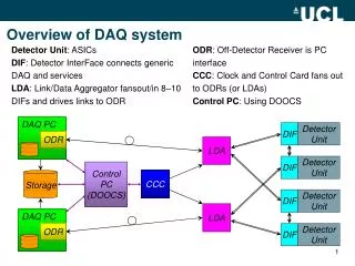
Eventdata (100kHz) ROI data (100kHz) Event Clear Request data Request data L2 decision L2 details ROI data Assign event L2 decision End of event To EventFilter (3kHz) Generalities : ATLAS DAQ ROS pROS DFM L2SV L2PU SFI Level1(L1) rate: 75 kHz min, upgradeable to 100 kHz Level2(L2) rate per ROS : 20 kHz ; L2 time budget per event: 10 ms EventBuilding(EB) rate : 3-3.5 kHz for 1.5 - 2 MByte events Recording rate: 200 Hz for 1.5 - 2 MByte events
Matching requirements • DataFlowManager(DFM), L2SuperVisor(L2SV): • previous work (TDR) has shown currently available hardware can match the requirements. • ReadOutSystem(ROS), SubFarmInput (SFI): • Latest studies will be presented in this talk • L2ProcessingUnit (L2PU): • Since the physics algorithms for event selection are not finalized, only time to fetch fragments from ROS will be compared to computation budget. • Networking: • Discrete event simulation tool will be used to scale from prototype setup up to final ATLAS size.
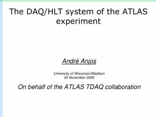
T6 – 31 ports EB / L2 Setups L2: up to 14L2PUs up to 6 L2SVs up to 8 ROSs FastIron – 64 ports Few FAST ROS EB: up to 16SFIs Up to 24 ROSs
EventBuilding Rate ROS : 12 emulated input channels, 1kB /channel SFI : No output to EF Solid lines: ROS=2GHz 9.66 kHzx12.4 k = 120MB/s ROS NIC limit Dashed line: ROS=3GHz 8.55 kHzx12.4k=106MB/sROS cpu limit 110MB/s per SFI NIC limit • Small & Large systems have the same max EB rate no penalty as event size grows • Can run 24 ROS vs 16 SFI EB system stably • Faster ROS does a better job (we hit the io limit) More ROS = Bigger Events !
Scaling in EB throughput • EB throughput scales linearly with Nb of SFIs • No show-stoppers • Possible to estimate the rate of any EB system in the prototype setup
Determining Number of SFIs Typical ATLAS event size 60% bw 90% bw Requirement: 3-3.5 kHz of EB for 60-70 % bandwidth usage per SFI • At typical event size of 1.5 Mb, 60 SFIs (2.4 GHz SMP) are enough • Output to EF + extra SFIs for safety margin should be considered • 100 SFIs (2.4 GHz SMP) would easily handle 3-3.5 kHz 1.5-2MB events
Level2 Rate • dummy algorithms in L2PUs • 6 concurrent ROI collection per L2PU • Linear scaling when ROS is not the limiting factor ROS cpu limited
L2 Time budget • If 500 L2PU 3 GHz SMP is used • 10 ms /event at 100 kHz L1 rate for L2 decision • Worst case of 16 ROLs all from different ROS < 0.8ms Longest ROI fetch: 13-16 ROL Requirement: 10 ms event for L2 decision, ROI fetch time << 10ms
ROS24 ROS19 L2P01 L2P14 Foundry EI … ….. … DFM pROS Combined setups: EB + L2 ROS18 … … ROS01 Foundry FastIron 800 BATM T6 L2SV01 … SFI01 L2SV06 SFI(O)1 - 16
Small system:3ROS x 2SFI x ..12 L2PU Plateau: ROS cpu limit Since the Max rates for EB and L2 are known, Use the plateau region to calculate the ROS cpu utilization for “clear” task
Analysis for ROS cpu CPU= REB×CPUEB + RL2×CPUL2 + RL1 ×CPUCl • CPUEBis the CPU power spend by the ROS on 1 kHz of Event Building • CPUL2is the CPU power spend by the ROS on 1 kHz of Level 2 ROI • CPUClis the CPU power spend by the ROS on 1 kHz of Event Clears + including clears ** using 2 NICs simultaneously Requirement: 100 kHz L1, 20 kHz L2, 3-3.5 kHz EB 2GHz ROS needs: 20x0.06061 + 3x0.2252 + 100x0.0074= 2.6 > 2.0 3GHz ROS needs: 20x0.05564 + 3x0.20274 +100x0.0083= 2.55 < 3.06
Combined system Largest possible system using 2GHz ROS • 18ROS x 16SFI x 12 L2PU runs stably
EB=3 kHz, acc=3% L2 = 20kHz L1=100 kHz Meeting requirements with 3 GHz ROS • Good agreement between data and simulation • 3 GHz ROS can do 20 kHz L2 & 3 kHz EB at 100 kHz L1
Final system Simulation -1 • 160ROS x 110SFI x N L2PU • Using concentrating switches for PUs (61) • Realistic Trigger Menu & ROI distribution Stable @ 95 kHz Stable @ 75 kHz
Final system Simulation -2 at2sim: 127ROS, 110 SFIs, 504 L2PUs with concentrator switches 120 100 L1 rate (kHz) 80 60 40 # events in L2 EB latency (ms) 20 Slowest ROS Q 0 time (s) 0 2 4 6 8 10 • Final size system runs smoothly with fast ROSs (3.06GHz)
Conclusions - I • 3GHz ROS can do 3kHz EB & 20kHz L2 • we need ~140 such nodes • Dual 2.4 GHz SFI can do 3kHz EB at 60% of line-speed • We need ~100 such nodes • Dual 3GHz L2PU can do ROI collection better than 8% of its time budget • We need ~500 such nodes • The largest test system was 18x16x12 • No scalability/functionality problems observed
Conclusions - II • at2sim of the final setup:160x100x ..500 • Scaling from 20% to 100%: • no surprises, no queues, no anomalies • Network: we can handle extreme traffic caused by ultra-fast L2 PUs without algorithms • Prototype L2PUs running @ 12.5 kHz, ~25 times faster then in the final system
Next Steps • Test: Prototype custom hardware with 2 input channels • Preseries: 10 % setup down in the ATLAS cavern • A bigger switch (128 ports) will be bought • Merge with existing prototype setup • Time scale: Q2 / 2005 • Networking aspects: scalability & performance • Separate test bed • Dedicated hardware (line-speed @ any Frame-size) • Stress testing candidate switches
Hardware inventory • Networking • 1 EB switch: Foundry FastIron 800 – 62 Ports • 1 L2 switch: BATM T6 – 31 Ports • 1 X-over switch: Foundry EdgeIron – 10 Ports • PCs (intel Xeon, 64bit/66MHz PCI) • 31 Tower Uni-proc. (2.0 GHz) • 25 used as ROS for scaling studies • 06 used as L2SVs • 01 used as DFM • 16 Tower Dual-proc. (3.06 GHz) • Used as L2PUs • 5 used as ROS for performance studies • 16 rack mountable Dual proc. (2.4 GHz) • Used as SFIs
EFD setup ROS1 ROS2 EFD1 EFD2 DFM EFD15 SFI
EFD Studies No EF output Single SFI: small events, WORST case. 40% performance loss
Data Emulation ROS input emulation vs Prototype Hardware