System Performance of ATLAS SCT Detector Modules
300 likes | 452 Vues
System Performance of ATLAS SCT Detector Modules. Peter W Phillips Rutherford Appleton Laboratory. Overview. This presentation aims to give an introduction to activities at the ATLAS SCT System Test. Introduction to ATLAS SCT Barrel and End-cap Modules Power Distribution System Redundancy

System Performance of ATLAS SCT Detector Modules
E N D
Presentation Transcript
System Performance of ATLAS SCT Detector Modules Peter W Phillips Rutherford Appleton Laboratory
Overview This presentation aims to give an introduction to activities at the ATLAS SCT System Test. • Introduction to ATLAS SCT • Barrel and End-cap Modules • Power Distribution System • Redundancy • System Test DAQ and Test Methodologies • Results from the Barrel System Test • Results from the Forward System Test • Summary
The Barrel Layout 2112 Barrel Modules mounted on 4 Concentric Barrels, 12 to each Row
Barrel + End-Cap 1976 End-cap Modules mounted on 9 disks to each end of the barrel region
The End-Cap Layout Rear of Disk 3 Showing Middle Modules Three Module Designs Of different Radial Geometries Front of Disk 3 Showing Outer and Inner Modules
The Barrel Module Each barrel module uses two pairs of Silicon Microstrip detectors, giving a total strip length of approximately 12cm. A small stereo angle of 40 mRad is engineered between the two sides to give positional information in two dimensions. The module is read out by 12 ABCD3TA ASICs mounted on a Copper/Kapton hybrid laminated onto Carbon-Carbon Bridges. The module Baseboard is built around a sheet of VHCPG (Very High thermal Conductivity Pyrolytic Graphite): conductive electrically and thermally.
The End-Cap Module • Three Designs of different Radial Geometries: Outer, Middle and Inner modules. (Outer is shown) • Small Angle Stereo (40 mRad) • 6 or 12cm strip length • Copper/Kapton hybrid laminated onto Carbon-Carbon substrate • 12 ABCD3TA ASICs • DORIC and VDC ASICs for optolinks mounted on the hybrid • PIN diode and VCSELS mounted on plug–in PCB • “wiggly” power tape mates directly with hybrid • TPG (Thermal Pyrolytic Graphite) Module spine: conductive electrically and thermally
Redundancy Within a module a token passing scheme is used to control the transfer of data to the master chip for onward transmission. This scheme incorporates several redundancy options such that, should any single chip fail, the remaining chips can still be read out. In the case that a module’s primary clock/control should fail, it can be fully configured and operated using the clock/control stream of the neighbouring module.
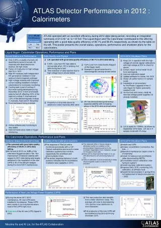
Type IV Conventional Cable, (<100m) Type III Conventional Cable, (<25m) Type II Conventional Cable, (Barrel:<7m Endcap: <5m) Type I Aluminium/Kapton, Low Mass Tape (50 mm Al) PPF0 (endcap only) “Wiggly” Tapes Power Distribution System LV and HV Power Supply PP3 Cable-Cable Connection (PP2) PPB1 (barrel) PPF1 (endcap) Module
Readout System Although the system test is being used as a proving ground for the final ATLAS SCT off detector electronics and power supplies, the majority of studies to date have used a set of custom VME modules. The VME crate is interfaced to a PC running Windows NT, or more recently Linux, by means of National Instruments’ PCI-MXI2-VME interface set. SCT module configuration and data acquisition is performed by the SCTDAQ software package.
SCTDAQ Software Architecture Static C libraries handle the basic communication with the VME boards. Higher level functions are implemented in a small number of C++ classes, linked with the static libraries and some libraries of the ROOT framework to form a shared library “STDLL”. Simple tests and configuration changes may be performed directly from the ROOT console; more complex tests have been implemented in the form of additional interpreted macros.
S-Curves and Fitting The ATLAS SCT has a binary architecture, however analogue information may be extracted by scanning chip thresholds. The complementary error function is fitted to threshold scan data: the mean corresponds to the threshold at which 50% efficiency is achieved for pulses of the designated magnitude and the sigma is a measure of the noise. The gain and input noise (ENC) of a module may be calculated from repeated instances of the threshold scan with differing injected charges.
Test Procedures Three Point Gain Threshold scans are performed for injected charges of 1.5, 2.0 and 2.5fC. In each case a complementary error function is fitted to the data: the mean corresponds to the threshold at which 50% efficiency is achieved for pulses of the designated magnitude and the sigma is a measure of the output noise (in mV). The gain of each channel is calculated from a linear fit to the fit results for the three scans. The output noise from the scan taken with 2.0fC injected charge is divided by the gain to determine the input noise (in fC or ENC). Single Threshold Scan A single threshold scan is performed for an injected charge of 2.0fC. The input noise is estimated from the measured output noise and the known average gain of each chip, which has been shown to remain constant over periods of many hours. This is one of the fastest methods that can be used to make comparative noise measurements.
Test Procedures Noise Occupancy Scan A threshold scan is performed without charge injection to determine the noise occupancy of each module as a function of threshold. Analysis of the data permits an estimation of the (Gaussian) noise of each module by means of a linear fit to a graph of ln(occupancy) vs Qthr2 (fC2). Deviation from this line, notably at higher thresholds, is indicative of non-Gaussian behaviour such as the presence of common mode noise. Repeated Noise Occupancy Here the modules are configured to a fixed threshold and repeated measurements of noise occupancy are made to monitor the stability of the system. Events are recorded sequentially: each complete event must be processed by MuSTARD before the next L1A trigger is broadcast to the modules. The threshold chosen for such studies is typically 1fC, the nominal operating threshold of the ATLAS SCT.
Test Procedures Correlated Noise Studies Data is acquired in the same manner as for a Noise Occupancy measurement, however each event is now written to a file. Analysis of the common mode component of the noise may be performed offline. Multiple L1A Studies Two L1A triggers are sent to the module, separated by a specified number of clock periods. The first event of the pair is thrown away leaving the second event to be histogrammed. By varying the spacing of the two triggers the occupancy of the modules is determined at various points during the readout cycle. In ATLAS, events will be recorded as data transmission is taking place: it is important that any electrical activity correlated with data transmission does not feed back to the front end.
The Barrel System Test 12 Modules in a row on the System Test Sector
Grounding and Shielding One important aspect of the G+S scheme is the interface between each module and its cooling block. The default solution places a “shunt shield” between the module and its cooling block. Any variation in the potential of the cooling block will now induce current on the shunt shield rather than the module baseboard. To further control any currents that may flow through the cooling pipe, each one is split into two electrically isolated halves to match the routing of the services. The alternate solution makes a DC connection between the cooling pipe and the module ground reference, minimising any difference in potential between the two. In parallel with this the cooling pipe is no longer split into two halves.
Signal Generator Noise Injection Into the Barrel Shield PPB1 PPB1 1W 1W Copper Sheet (Heat Spreader) ThermalShield
Comment • The final choice of shield configuration has not yet been made • The decision will be made after noise injection studies have been repeated with pre-series production components • For the time being, both options are preserved. • Studies continue…
Grounding and Shielding • All cooling blocks tied to disk, and to the shield, through a system of foils applied to the disk’s surface. • A shunt shield was integrated into the design of the K5 forward module to protect the module spine from noise currents on the cooling block. • A second shunt shield protects the module ground reference from noise currents on the cooling block. • An alternate proposal places a DC connection between the module ground reference and its cooling block. At the system test this has been implemented by placing a copper braid between the cooling block and AGND at the module power connector. • The latter configuration has been studied with and without a secondary tie between each module’s digital ground line and the shield at PPF0. • Initial studies have shown good performance without noise injection. Studies of grounding and shielding are ongoing.
Time Dependency of Noise Noise decreases with time. The time constants involved vary from module to module and can be as long as one hour. This has now been understood as an intrinsic time dependence of the detector interstrip capacitance.
Noise by Three Point Gain Method NB. Figures normalised to chip temperature expected in ATLAS (2oC)
Summary A system test of the ATLAS SCT has been established at CERN. An extensive set of tools has been developed to probe the performance of the system. These tools have facilitated studies of several grounding and shielding configurations. The studies will continue using pre-series production components.