Download
1 / 20
210 likes | 370 Vues
Systematic Study of Micro-Discharge Characteristics of ATLAS SCT Modules. K. Hara, T. Kuwano, S. Shinma (Univ. of Tsukuba) Y. Ikegami, T. Kohriki, S. Terada, Y. Unno (KEK).

E N D
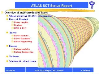
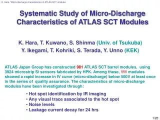
K. Hara, “Micro-discharge characteristics of ATLAS SCT modules Systematic Study of Micro-Discharge Characteristics of ATLAS SCT Modules K. Hara, T. Kuwano, S. Shinma (Univ. of Tsukuba) Y. Ikegami, T. Kohriki, S. Terada, Y. Unno (KEK) ATLAS Japan Group has constructed 981 ATLAS SCT barrel modules, using 3924 microstrip Si sensors fabricated by HPK. Among these, 111 modules showed a rapid increase in IV curve (micro-discharge) below 500V at least once in the series of quality assurance. The characteristics of micro-discharge modules have been investigated through: • Hot spot identification by IR imaging • Any visual trace associated to the hot spot • Noise levels • Leakage current decay for 24 hrs
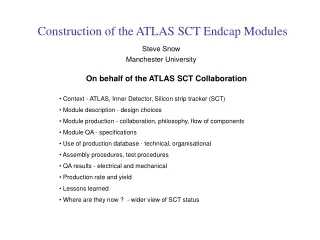
K. Hara, “Micro-discharge characteristics of ATLAS SCT modules ATLAS SCT Barrel Module 80um Si3N4 Al p-implant • 4 pcs of 64x64mm Si microstrip sensors (HPK 4” process) glued back-to-back onto a baseboard • flexible hybrid bridges over the sensors (This prevents thorough IR inspection) • 16um wide p-implants at 80um pitch • 22um wide Al electrodes • SiO2 and Si3N4 insulators design guideline: no touching/gluing on the strip face exceptions: vacuum sacking via clean-room paper & wirebonding HV tested up to 500V, maximum HV for innermost barrel.
K. Hara, “Micro-discharge characteristics of ATLAS SCT modules IV curves of Modules 1-200 Out of 981 modules B: micro-discharge modules 111 including 6 C: failure
K. Hara, “Micro-discharge characteristics of ATLAS SCT modules History of 71* MD Modules MD in sensors but never later Al overhang suppresses MD *71 modules were tested in the specified sequence (e.g. no 500V test in some sensors) tiny MD, VMD~500V,mostly IR imaging : temperature : humidity (module⇒LT) more MD in N2 damaged at module production? damaged at testing? IR hot spot imaging to understand the problem
K. Hara, “Micro-discharge characteristics of ATLAS SCT modules IR hot spot imaging 1&2: hot spot imageoverlaid on image with zero bias and some external light 3 1 2 HPK 512x512 pixel CCD with C4880 controller (16-bit imaging), cooled to -55oC by the Peltier Ileak>1uA for IR imaging procedure: 1. wide-angle lens covers the area ½ of the module (4 shots/module). under the hybrid is out of sense 2. microscope lens to localize 3. conventional image to visualize 2⇒3 requires a visible mark
K. Hara, “Micro-discharge characteristics of ATLAS SCT modules Visual images of the hot spot 1/5 A)7 modules with irregularly shaped p-implants problem of lithography module, 470V module, 450V MD first seen at Final, 450V VMD: +,390~470V 3/3/1 modules since “sensor”/module/final Images shown may be spectacular, but most of HPK sensors are clean, as we know…
K. Hara, “Micro-discharge characteristics of ATLAS SCT modules Visual images of the hot spot 2/5 B)7 modules with scratch-like trace module, 480V module, 490V module, 10V Isensor~2×nominal VMD: 10, 390, >460V 1/6 modules since “sensor”/“module” problem since sensor processing
K. Hara, “Micro-discharge characteristics of ATLAS SCT modules Visual images of the hot spot 3/5 C)5 modules with dots along Al module, 440V module, 425V VMD: 410~490V 4 modules since “module” 1 module since “LT” problem since sensor processing Incomplete cleaning? module, 490V
K. Hara, “Micro-discharge characteristics of ATLAS SCT modules Visual images of the hot spot 4/5 D)7 modules with red spots LT, 380V sensor, 420V sensor, 440V VMD: +,>460V (3/1/3 since “sensor”/”module”/”LT”) E)15 modules with black spots sensor, 350V module, 380V module, 260V VMD: +,>410V (3/9/3 since “sensor”/”module”/”LT”) droplets of, or impurities in photoresist
K. Hara, “Micro-discharge characteristics of ATLAS SCT modules Visual images of the hot spot 5/5 sensor, 430V module, 475V module, 425V F)8 modules with no visible/clear flaw VMD: +,>470V (1/6/1 since “sensor”/”module”/”LT”) G)12 modules not categorized* VMD: >400V (2/7/2/1 since “sensor”/”module”/”LT”/”final”) *No visible mark to localize the position (9) No time to take photo for scheduled shipping…(3) No visible damages, but clear IR hot spots : (problem underneath the Al structure?) problem since sensor processing module, 475V
K. Hara, “Micro-discharge characteristics of ATLAS SCT modules Summary of hot spot classification 61 modules: IR spot identified module, 25V O)2 modules scratched/damaged by miss-handling (damages are recorded) ⇒ VMD~0V • 7 modules with irregularly shaped p-implants • B) 7 modules with scratch-like trace • C)5 modules with dots along Al • D)7 modules with red spots • E)15 modules with black spots • F)8 modules with no visible/clear flaw • G)12 modules not categorized *2 modules are in 2 different categories These, except O), are problems since sensor processing. 50 modules: IR spot not identified 4 modules: recorded damage (noise is large at damaged strips) 19 modules: too tiny leakage for hot spot detection (I< 1uA) ~10 modules: hidden under the hybrid (16% in area x 61 modules identified/0.84) ~17 modules: large enough leakage but IR not detected “Dark modules” Q: what are they?
K. Hara, “Micro-discharge characteristics of ATLAS SCT modules Micro-discharge onset voltage: 111 modules “Dark modules” 1 IR: Type B) 5 damaged ~Type O) tiny MD @500V since sensor ? since LT damaged Investigate using the noise distributions
K. Hara, “Micro-discharge characteristics of ATLAS SCT modules Noise of “Dark” modules (1/2) typical MD noise Vb=410V I=2.5mA Tdecay = 0.6h no hot spot / no flaw associated ⇒flaw under hybrid ? flaw not visible ? Vb=260V I=2.5mA Tdecay = 8.6h Not a typical MD noise Typical module with flaw at bias ring ? (since sensor)
K. Hara, “Micro-discharge characteristics of ATLAS SCT modules Noise of “Dark” modules (2/2) typical MD noise Tdecay=7.2h Vb=330V I=1.5mA Tdecay = 7.2h 5 modules 4 modules: typical MD noise no flaw associated Al short Tdecay 2.1h 0.14h 0.03h 0.83h no inspection made Noise distribution consistent with luminous MD
K. Hara, “Micro-discharge characteristics of ATLAS SCT modules History of 71 MD modules (II) all MD modules Clear flaw identified: MD not detected at sensor probing ⇔MD has developed… Number of MD modules IR failed Tiny MD IR failed & I>1uA “Dark modules” history consistent with luminous MD
K. Hara, “Micro-discharge characteristics of ATLAS SCT modules Leakage Current Decay at 500V Decay time : typically < 1 h ATLAS group agreed to evaluate leakage decay time for MD modules MD is tendered with time measured for >24 h 3 damaged modules showed instable behavior: no decay assigned
K. Hara, “Micro-discharge characteristics of ATLAS SCT modules Leakage Current Decay at 500V hot spot not identified hot spot identified The decay time is typically less than 1hr for most modules. But not all… Most of the modules decrease the leakage to the level of genuine modules within 24hrs. But not all… YES “Dark modules” tend to be irregular ⇔ modules with longer decay time is not luminous
K. Hara, “Micro-discharge characteristics of ATLAS SCT modules Flaws of modules with longer leakage decay Td=10h Td=4.7h Td=1.3h Td=7.2h Td=6.4h Td=1.7h Td=1.1h Td=4.6h Noise What are the characteristics of Modules with longer decay? tend to be “no flaw”, or “mild” defects… Hot spot seen VMD=25V
K. Hara, “Micro-discharge characteristics of ATLAS SCT modules Summary Among 981 ATLAS SCT barrel modules constructed by Japan, 111 modules showed micro-discharge below 500V. 6 modules are damaged at assembling or testing 59/105 modules are IR hot spots identified: 2/3 incomplete photoresist processing, cleaning,* 1/3 no clear flaw associated 46/105 modules are IR failed: 2/5 (I<1mA) tiny micro-discharge 3/5 (I>1mA)noise distribution consistent with luminous MD no anomaly in the MD history in test sequence leakage decay time tends to be longer (Td>1h) (“mild” defects for modules with longer decay time?) MD is humidity dependent (sensor probing in air vs module operation in N2) MD develops (some sensors with clear flaws were OK at sensor probing) *HPK 6” process is better
K. Hara, “Micro-discharge characteristics of ATLAS SCT modules Installation to the ATLAS Barrels 4 barrel layers Japan cluster (981 modules) 83 MD with VMD>350 &Tdecay<1h ⇒ outer 3rd/4th barrels 14 MD with 350>VMD>150 &Tdecay<6h⇒ spares 14 MD with (VMD<150 or Tdecay>6h) ⇒ FAIL other reasons (23 3rd/4th , 7 spares, 7 FAIL, 10 SQ) 823 modules ⇒ any barrel