Download
1 / 20
200 likes | 420 Vues
Detector Control System of the ATLAS MDT system. Anastasios Iliopoulos N.T.U.A. XXV HSSHEP Workshop Athens, 28-31/3/2007. At a glance…. Power Supply of MDT chambers ATLAS Detector Control System PVSS and DCS frameworks Finite State Machine Graphic User Interface

E N D
Detector Control System of the ATLAS MDT system Anastasios Iliopoulos N.T.U.A. XXV HSSHEP Workshop Athens, 28-31/3/2007
At a glance… • Power Supply of MDT chambers • ATLAS Detector Control System • PVSS and DCS frameworks • Finite State Machine • Graphic User Interface • Features under development
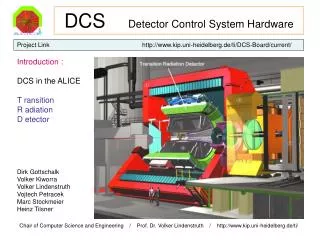
Power Supply of MDT chambers • Two multilayers of drift tubes • High voltage & Readout sides • Each multilayer is operated by a separate high voltage channel (~3000V) • Low voltage (5V) is supplied to the Readout side
Detector Control System (DCS) • System to control the operation of a HEP experiment using computers • Increasing the complexity of an experiment • Organized control of a large amount of parameters • Continuous monitoring of the experiment • Automatic errors recovery procedures • Operation procedures become very easy – operators don’t need to be experts
ATLAS DCS Basic Structure ATLAS Track Detector Hadronic Calorimeter Muon Spectrometer Electromagnetic Calorimeter CSC MDT RPC Power Supply Monitoring Temperature, Magnetic Field High Voltage Low Voltage
ATLAS DCS Basic Structure PVSS DCS System DCS System Chambers (devices) OPC Server CAEN Power supply units
PVSS and DCS frameworks • PVSS II v3.6 by ETM: • Communication with hardware (e.g. CAEN Power Supply units via OPC server) • Storing data (Internal and external archiving – Oracle db) • Warnings and Errors handling • Built-in programming language C++ • Graphic Editor • JCOP and ATLAS Frameworks: • Extended features for programming and development • Organization of libraries, panels and scripts • Naming and Look conventions (system names, panel names, panel size…) • FSM user interface and integration/programming features
Finite State Machine • Mike Bachtis & Anestis Iliopoulos: Development of a PVSS project for control and monitoring the power supply of MDT chambers • The heart of the project is a FSM • FSM decides HV and LV channel States by reading the status bitmask Status bitmask=OnOff*20+rUp*21+rDown*22+OvC*23+…+Trip*29+… • Decides the State and the Status for the chamber • Rules for State and Status propagation to upper levels • State defines the operation mode of the system (ON, OFF, etc) • Status defines how well the system is working (OK, Warning, Alarm, etc)
Finite State Machine PROPAGATION RULES • State • If All Channels OFF then Chamber State = OFF • If only LV is ON then Chamber State = STAND_BY • If LV is ON and ½ HV is ON then Chamber State = ON50 • If LV is ON and both Multilayers are ON then Chamber State = ON • Else Chamber State = UNKNOWN • Status • If a channel trips or returns h/w error then Chamber Status = ALARM • If an overcurrent happens then Chamber Status = WARNING • Else Chamber Status = OK
MDT FSM Structure State & Status ← GCS: Overall control of the detector ATLAS Commands MDT ← SCS: Full local operation of sub-detector Barrel A Barrel C EndCap C EndCap A ← TTC Partitions → INNER MIDDLE OUTER ← Layers BMS1C14 BML1C01 ← Chambers Blanc font: Control Units (CU) Purple font: Device Units (DU)
User Interface • First step: FSM Hierarchy Creation
User Interface • First step: FSM Hierarchy Creation • Automatic FSM generation • Automatic set of all necessary parameters • Option of reading chamber parameters from a simple text file
User Interface • Second step: Start FSM and main project panels using Device Editor and Navigator
Features Under Development • Configuration DB Tool • Storing configuration schemes to oracle db for quick apply on the system (Run, Beam_Wait, Cosmics etc) • Conditions DB Tool • Storing voltage and/or current values during run time to oracle db
NTUA DCS Team: T. Alexopoulos, G. Tsipolitis, E. Gazis M. Bachtis, C. Tsarouchas, A. Iliopoulos Thank you !