Download
1 / 15
150 likes | 414 Vues
The Hardware of the ATLAS Pixel Detector Control System. Tobias Henss, University of Wuppertal. Content. I. Pixel Detector II. DCS Overview III. Hardware IV. Summary. 1744 modules 3 layers with r = 5, 9, 12 cm 3 space points for | η |<2.5 80 million Pixels (~90% ATLAS)

E N D
The Hardware of the ATLAS Pixel Detector Control System Tobias Henss, University of Wuppertal
Content • I.Pixel Detector • II.DCS Overview • III.Hardware • IV.Summary „The Hardware of the ATLAS Pixel Detector Control System “
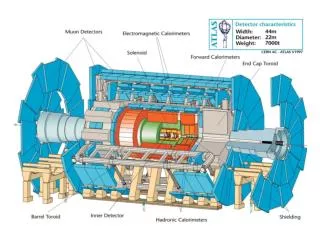
1744 modules 3 layers with r = 5, 9, 12 cm 3 space points for |η|<2.5 80 million Pixels (~90% ATLAS) main task: vertex-reconstruction ~6,5 kW -7°C operation temperature evaporative C3F8 cooling system I.Pixel Detector 1.3 m The Pixel Detector „The Hardware of the ATLAS Pixel Detector Control System “
I.Pixel Detector HV (< 700 V) VDD (~1.7 V) VDDA (~2.1 V) Temperature Pixel Detector Geography • Disc • BLayer • Layer1 • Layer2 • max. 26 parallel cooling circuits (PCCs) per layer • 4 half-staves / 2 sectors per PCC • 6 / 7 modules per half-stave Cooling (-7 °C) LV (< 12 V), SC-OLink „The Hardware of the ATLAS Pixel Detector Control System “
II.DCS Overview Hardware Requirements • optical link • laser interlock • supply and control • low cost / manpower • common parts (ATLAS ELMB) • common interfaces (CAN, TCP/IP) • grounding sceme • floating • prevention of transients • use of opto-couplers or transformers • high power density (~6.5 kW) • thermal interlock • radiation • radiation hard / tolerant devices • enable for long distance powering (LV -> regulators) • granularity • costs for power supplies • high availability „The Hardware of the ATLAS Pixel Detector Control System “
III.Hardware The DCS Hardware Environm. Module T HV VDD VDDA Optoboard T Sensors VVDC VPin VISet Data Cover Regulator Station T BBIM BBM Distance from interaction point Interlock HV-PP4 LV-PP4 System Iseg Wiener SC-OLink Data Door BOC CAN-Open protocol TCP/IP CAN-Open protocol DCS-PCs „The Hardware of the ATLAS Pixel Detector Control System “
Wiener LV supply: LV for the modules VDD and VDDA 12 channel power supply max 12 V / 11.5 A floating protections: over-voltage, over-current III.Hardware Low Voltage Environm. Module T HV VDD VDDA Optoboard T Sensors VVDC VPin VISet Data Cover LV-PP4: • mapping of regulator boards to PS channels • uses ELMB • current measurement of plus lines: • 2- 10 mA tested precision • 0 V to 2 V range • opto-decoupled • current measurement on return lines can be added for selected boards Regulator Station T BBIM BBM Distance from interaction point Interlock HV-PP4 LV-PP4 System Iseg Wiener SC-OLink next slide Data Door BOC CAN-Open protocol TCP/IP CAN-Open protocol DCS-PCs „The Hardware of the ATLAS Pixel Detector Control System “
III.Hardware Regulator Station • protects sensitive front end chips against transients • 12 regulator boards/station • 1 controller board per station(FPGA Actel APA075 internal control, ELMB communication to outer world • reg. board houses 16 regulator circuits (all you need for one half stave) • key component: ST LHC4913 • adjustable output voltage 0 to 12 V via digital trimmers • external on/off control „The Hardware of the ATLAS Pixel Detector Control System “
Iseg HV supply: module depletion HV 16 channel power supply max 700 V / 4 mA floating protections: over-voltage, over-current III.Hardware High Voltage Environm. Module T HV VDD VDDA Optoboard T Sensors VVDC VPin VISet Data Cover Regulator Station T BBIM BBM Distance from interaction point HV-PP4: • mapping of modules to PS channels (modularity 6/7 or 2) • uses ELMB • objective of current measurement (to be implemented): • 5% precision • 0.4 mA to 4 mA range • opto-decoupled Interlock HV-PP4 LV-PP4 System Iseg Wiener SC-OLink Data Door BOC CAN-Open protocol TCP/IP CAN-Open protocol DCS-PCs „The Hardware of the ATLAS Pixel Detector Control System “
Supply and Control for the Opto Link (SC-OLink): floating outputs between 5-20 V and 20-800 mA controlled and monitored by an ELMB decoupled via opto-couplers / transformers 12 bit DAC with SPI interface hardware current limitation III.Hardware SC-OLink Environm. Module T HV VDD VDDA Optoboard T Sensors VVDC VPin VISet Data Cover Regulator Station T BBIM BBM Distance from interaction point Interlock HV-PP4 LV-PP4 System Iseg Wiener SC-OLink Data Door BOC CAN-Open protocol TCP/IP CAN-Open protocol DCS-PCs „The Hardware of the ATLAS Pixel Detector Control System “
III.Hardware prevention of human injuries (lasers) prevention of detector damage (temperature) fast reaction time hardware based self-certifying (by monitoring) radiation tolerant flexible logic (changing modularities) fine granularity Interlock System Requirements „The Hardware of the ATLAS Pixel Detector Control System “
Interlock System: receives digital signals and creates interlocks distributes interlocks to the PS uses ELMBs for monitoring III.Hardware BBIM: digitization / discrimination of analog temperature values uses ELMB for monitoring Interlock System Environm. Module T HV VDD VDDA Optoboard T Sensors VVDC VPin VISet Data Cover Regulator Station T BBIM BBM Distance from interaction point Interlock HV-PP4 LV-PP4 System Iseg Wiener SC-OLink Data Door BOC CAN-Open protocol TCP/IP CAN-Open protocol DCS-PCs „The Hardware of the ATLAS Pixel Detector Control System “
III.Hardware action on individual channels or small group of channels action on all channels HV LV SC-OLink BOC HV LV SC-OLink BOC TModule X X TRegulator X X X TOptoboard X IBocDoor X X IOptoboardCover X X IDSS X X X The Interlock System Interlock controlled Devices: 1100 Incoming Signals: 2150 BBIM Logic Units Interlock Distribution Boxes PP1 Box BOC-I-Box „The Hardware of the ATLAS Pixel Detector Control System “
V.Backup TCP/IP: only Wiener private network CAN: > 500 nodes all but Iseg ELMB-type ~5 s update time Connection to Control PCs Environm. Module T HV VDD VDDA Optoboard T Sensors VVDC VPin VISet Data Cover Regulator Station T BBIM BBM Distance from interaction point Interlock HV-PP4 LV-PP4 System Iseg Wiener SC-OLink Data Door BOC CAN-Open protocol TCP/IP CAN-Open protocol DCS-PCs „The Hardware of the ATLAS Pixel Detector Control System “
The DCS is responsible for: control of all power supplies monitoring of all process parameters the interlock safety system It makes use of: a variety of sensors many custom made components that all use the ELMB: Supply and Control for the Opto Link (SC-OLink) Regulator Station Logic Unit (LU) Interlock Distribution Box (IDB) IV.Summary & Outlook Summary • Building Block Monitoring (BBM) • Building Block Interlock Monitoring (BBIM) • High-Voltage Patch Panel 4 (HV-PP4) • Low-Voltage Patch Panel 4 (LV-PP4) „The Hardware of the ATLAS Pixel Detector Control System “