Download
1 / 13
130 likes | 285 Vues
Detector Control System of Tile Calorimeter. Giorgi Arabidze (UoA) Tile Cal DCS team. Outline:. Introduction Control of Low Voltage Power Supply system The High Voltage control Infrastructure related systems Connection with external systems Usage of Conditions and Configuration DB

E N D
Detector Control System of Tile Calorimeter Giorgi Arabidze (UoA) Tile Cal DCS team Giorgi Arabidze UoA
Outline: • Introduction • Control of Low Voltage Power Supply system • The High Voltage control • Infrastructure related systems • Connection with external systems • Usage of Conditions and Configuration DB • Available tools Giorgi Arabidze UoA
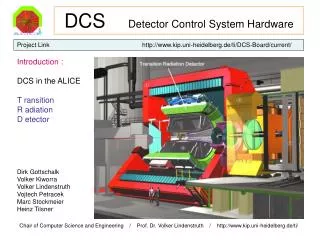
Introduction • For DCS implementation commercial SCADA software is used – PVSS II • DCS includes following main, infrastructure and calibration systems • The main systems • The Low Voltage Power Supply system • The High Voltage distribution system • Detector calibration systems • The Cs calibration system • The Laser calibration system • Infrastructure related systems • Detector water cooling system and rack monitoring • Detector Safety System (DSS) Giorgi Arabidze UoA
Hierarchy of Tile Cal DCS • Five Control Stations are used for implementation of BE system of DCS • 1x Sub-detector Control Station (SCS) • Allows complete operation of sub-detector • Communication with DAQ, DSS, Calibration and infrastructure systems • Handles Bulk Power Supplies – 200 and 830/900 V • 4x Local Control Station (LCS) • Handles LVPS and HV systems • VME crate control Giorgi Arabidze UoA
The DCS for LVPS system (I) • The LVPS system is composed by three devices: • 200V bulk PS – provides input voltages to fLVPS devices • fLVPS – DC-DC convertor device, provides input voltages for FE electronics • AUX boards – Control device for fLVPS devices Giorgi Arabidze UoA
The DCS for LVPS system (II) • Used communication protocols: • CAN Open – fLVPS and AUX board devices • Mod Bus – 200V Bulk PS • Monitoring of system parameters with 10 sec frequency • Acquiring 4346 parameters per partition • Two levels of message conversion for ELMB based readout: • Raw to physical units, i.e. voltages, currents and temperatures • Using calibration constants to adjust output and sense line voltages Giorgi Arabidze UoA
The DCS for LVPS system (III) • The Low Voltage switch ON procedure • Switch ON 200V PS channels • Load calibration constants from Configuration DB • Set output voltages to minimum and allow output voltages to FE electronics • Rump-up voltages to nominal after 40 sec of stabilization time Giorgi Arabidze UoA
The DCS for HV distributor system (I) • Based on HV Bulk PS – 830/900 V • Provides common voltage for each set of PMTs (48 PMTs ) • The HV regulator system – HV OPTO • Provides fine adjustment of the voltage for each PMT • Voltages are controlled by the controller HV_MICRO • Communication protocols: • Serial RS-422 with HV Bulk PS • CAN Open with HV_MICRO controller Giorgi Arabidze UoA
The DCS for HV distributor system (II) • The PMT voltages are monitored with frequency of 10 sec • Monitoring 4352 parameters per partition • The C++ application is used for communication • The PMT states are defined by the internal firmware of HV_MICRO controller Giorgi Arabidze UoA
Connection with external systems • Connection to DAQ and Calibration systems established through SCS • Using DIM/DNS interface • Provides possibility to implement command/data exchange • Communication with DAQ system • DCS publishes state of each Tile Cal module to DAQ system • Information about DAQ activities (run type and number) available in DCS • Calibration systems • Cs calibration system has possibility to retrieve/apply PMT voltages • Parameters of Laser system are displayed on panels of DCS Giorgi Arabidze UoA
Tile Cal Finite State Machine (FSM) • FSM – top level software for detector operation • To be used by shifters – common interface for all sub-detector • FSM granularity • CU – CAN/Mod Bus/serial branch • LU – Tile Cal module • DU – Channels of individual device units • Implemented commands on CU level • GOTO_READY – Switches ON all device units below • GOTO_STANDBY – Switches ON only LV supply part of sub-detector • GOTO_NOT_READY – Switches OFF all DUs below • RECOVER – Used after power cuts on Tile UPS Giorgi Arabidze UoA
Tile Cal Finite State Machine (FSM) Giorgi Arabidze UoA
Usage of Configuration and Conditions DB • Configuration DB – store data related with detector configuration • Calibration constants for individual output and sense line voltages • Nominal output voltages • Condition DB – store detector relevant information for understanding detector behavior • Voltages, currents and temperatures • Using smoothing to reduce amount of data Giorgi Arabidze UoA